Hydroponics System - ECE4760 Final Project
By: Jessica Henson & Leo Davies
Introduction:
Our project is a countertop sized, controlled environmental hydroponic system for fresh produce integral to our daily diets year around! We spent the past few weeks building a 12 inch by 12 inch by 16 inch in-home garden with climate control surrounding water temperature, water level, and light resources. Our first week was spent designing and laser printing an acrylic box with space to insert two fans, a water pump, and wires. Then we began the process of soldering three motor control circuits, as seen in lab 3 of ECE4760. For our second week, we finalized the motor control circuits and tested them with fans, heating pads, and the water pump. We also decided on RPi Pico GPIO pins to connect each motor control circuit two, along with researching and determining the necessary pins for temperature sensor and ultrasonic sensor. Our final week and a half was spent debugging the circuitry and programming the raspberry pi to receive a desired temperature input, change the water temperature with the heating pads and fans accordingly, and control the water level inside the grow tray with the water pump and reservoir.
High-Level Design:
The idea for our project came from a culmination of mutual interest and history working with hydroponics and indoor growing systems. We had researched previous projects and had seen successful builds, so that gave us hope when designing our system. The first step we took to plan our project was figuring out what sensors and devices we needed to monitor and manipulate our environment.
We did some research online and found the most important conditions to maintain in a hydroponic system were constant water level and temperature. So we looked into a temperature sensor and water level sensor. We found this temperature sensor, which operates off the 1-wire signaling scheme. As for water level, we found that ultrasonic sensors could accurately measure distances off water surfaces.
Next, we had to find devices that could change both temperature and water level that the Pico could control. To regulate temperature, we bought both heating pads and cooling fans. For the water level, we bought a submersible pump to refill the container as water is consumed by the plants. All of these could be controlled by a motor circuit we had implemented in an earlier lab.
We had to consider the quantity of sensors and devices we were ordering to ensure we had enough space on the Pico. The Pico has plenty of GPIOs, some of which have different communication capabilities. We had to ensure that as we added devices, we had enough room on the Pico to properly communicate with the device. Another consideration we had was the complexity added to both the hardware and software with each device added. Each device added to the system would take up breadboard space and require more software configuration and balance within the code. For the scope of this project, we decided to implement the devices from above, and depending on the complexity of both the hardware and software, continue to add sensors and devices beyond that.
Another consideration we had was the safety of the electronics. We knew we were controlling and regulating a system with water, and we had to think thoroughly about how to protect the electronics from getting wet. We designed a box to try and isolate the two as much as possible. Using CAD software (Fusion 360), we designed the edges of a cube to contain our environment with the water tank and regulators, with small holes cut out. One hole on the side was for tubing for access to an external reservoir of water with our pump. We cut out holes on opposite sides of the walls for the fans to sit in, and then a hole in the top to run all of our wires from the environment to the hardware on top. By maintaining the electronics on top, we were able to keep it safe from the water.
Program/Hardware Design:
Once we had the physical build of our box, we began piecing together each sensor/device one by one, starting with hardware then working the software in. First, we started with the fans since we had worked with them before in lab 3. To use the fans, we needed to build a motor control circuit isolated from the microcontroller. This is due to the large voltage spikes that come off a DC motor when running, some of which can fry the microcontroller.
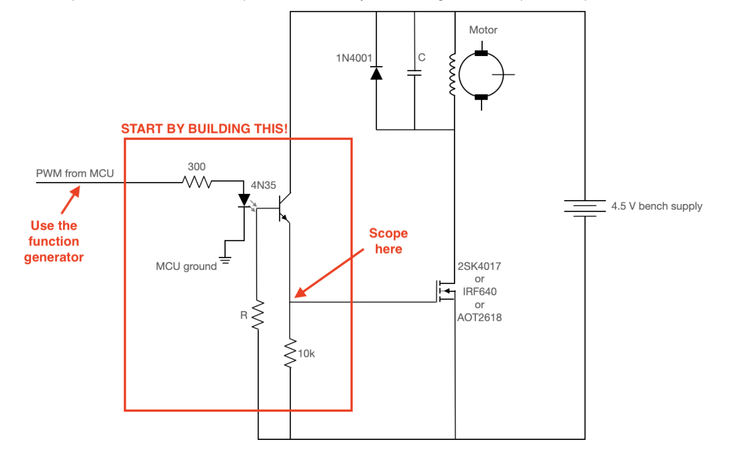
Figure 1: Motor control circuit
Above is an image of the motor control circuit we built. Starting with the components in the red rectangle (plus the bench power supply), we built it up component by component, checking each time that we were reading the correct signal on the motor side of the circuit. The two resistor values we used were 1MOhm and 10kOhm. The 4N35 component is an optoisolator, to separate the two circuits electrically. This allows us to send a PWM (pulse-width modulation) signal from our microcontroller to the other circuit through the electrical “translation” of the optoisolator. We were able to test this by sending a square wave with a specific duty cycle from the function generator, then read that same duty cycle, but with the 4.5 V amplitude on the other side using the oscilloscope. This ensured that we had the circuit built correctly thusfar.
We then built the rest of the circuit up around that. The two components in parallel with the motors help provide paths to ground for reverse polarity spikes and high-frequency noise. The capacitor started at 0.1uF, but could be increased depending on the noise. We hooked both fan motors up in parallel with those components, so we could control both fans with one circuit. This way, you could consider the two fans as one unit. We then soldered the components into a solder board so no wires would come loose. Once we had completed the circuit and tested it with the function generator, we began controlling the circuit with the microcontroller. We configured one of the GPIOs to send a PWM signal to the circuit. We then controlled it through a serial monitor input, asking for a duty cycle between 0 and 5000. From then on we could change the duty cycle and watch the fans speed up and slow down.
Next, we wanted to add in the heating pads. We built the same motor control circuit, with both heating pads in parallel, similar to the fans, to act as one unit. Both the fans and heating pads operated off 5V of power, so we used the same bench supply for both circuits. Again, we tested and debugged the circuit in the same way to confirm it was correct, then soldered it in. Similar to the fans, we integrated the software allow for open-loop control of the heating pads with the serial monitor. We configured a new GPIO to send out a PWM signal, and allowed user input to change either the fan or heating pad signals. This allowed us to turn on or off either the heating pads or the fans, similar to how we would eventually want the closed-loop system to operate.
Once we had the two devices to manipulate the temperature inside our environment, it made sense to get the temperature sensor working and adjusting the fans and heating pads based on it’s readings. The temperature sensor we used was from the 1-wire family of devices. This communication system allows multiple devices to communicate and be powered by one wire or bus. This system works by allowing the devices charge up a capacitor when the line is high, then use that charge for device operation and communication while the line is low. For us, we only had one device to operate on with this system, which made it easier to use. We found this example code online from Raspberry Pi, which happened to be interfacing with the exact device we had. We then used this to setup our temperature sensor and get readings off of it live. We then switched our open-loop control system to become closed-loop. We now had users input desired temperatures into the serial monitor, then based on the temperature sensor reading, turn on either the fans or the heating pads to adjust. We could then test our software implementation by inputting different desired temperatures and watching the fans or heating pads turn on and off respectively.
One issue we continued to encounter was how our code would get blocked waiting on a user to input their desired temperature. This meant that if the heating pads were turned on, for example, they would never turn off unless the user imputed a new number that was lower than what the current temperature was reading. We had two pieces of code, the serial monitor and the temperature control loop, operating as one. To account for this, we extrapolated the two into separate threads, one which could loop, and the other could stall waiting for an input. This way, we could constantly check the current temperature readings against the desired temperature and adjust the devices while simultaneously waiting for a new input from the user. From our example, the heating pads would turn off once the desired temperature was reached, and if the current temperature continued to rise due to momentum, the fans would turn on to cool it down.
Next, we went to implement the other closed loop control system we had, which was the pump/ultrasonic sensor loop. Again, to control the pump, we built and debugged the same circuit for the fans and heating pads. The only difference was that the pump required significantly more power, at 12V. As for the ultrasonic sensor, it operated off a trigger pin and an echo pin. We set each one up with a GPIO, and configured the trigger pin as a GPIO output, and the echo pin as a GPIO input. The ultrasonic sensor operated off a simple principle: send an ultrasonic signal out off the trigger pin, wait for a response from the echo pin, and measure the time it took for the signal to travel. Using that time and the speed of sound, you can calculate the distance from the surface the ultrasonic sensor is facing.
We initially implemented this software separately from the temperature loop for debugging and safety purposes. Since this part of our project involved water and turning on and off a pump, we wanted to be extremely cautious with it. We began by testing the pump out with an open-loop control, turning it on and off at our will. We then implemented a closed-loop control with the ultrasonic sensor, turning the pump on when it measured large distances and off when it measured close readings. We then tested this initially by moving the ultrasonic sensor closer and further from walls, watching the pump turn on and off as we went. Then, we began testing the system by placing the ultrasonic sensor in a hole in the lid of our plant reservoir, and having the pump fill up the reservoir until the ultrasonic sensor measured the correct distance. We played around with the that distance, eventually settling on a water level 2 cm from the top. This water level allowed the plants to sit and soak in the water, but kept it far enough away from the electronics like the ultrasonic sensor.
Finally, we were able to integrate both of these control loops into one program. In one thread, we had the serial monitor awaiting input on a desired temperature to control the heating pads and fans. In another loop, we had the temperature readings constantly compared to the desired temperature, and adjustments being made accordingly. Also in that loop, we had the ultrasonic sensor readings compare to a constant (2 cm), and the pump control adjust accordingly. After this, we had a fully operational environment with water level and temperature control all happening autonomously. The only user input required was the desired temperature.
Results:
We were successful in the overall goal of our project. There were a few sensors we would’ve included if given more time such as: the TDS sensor (for nutritional content of the water), a humidity sensor, and a separate pump/water reservoir to store a high PPB of nutrients. Outside of those two sensors and actuator, we had a lot of success. For sensors, we implemented a one-wire water temperature sensor and an ultrasonic sensor to measure the water level. For actuators, we implemented heating pads for under the grow tray, fans embedded in the walls, and a water pump to fill the grow tray. With everything implemented, we individually tested and combinational tested the components.
Our first implementation was that of the fans because we had done something similar in lab 3. We soldered a motor control circuit and ran the fans off of 5V. Our first tests were done with the function generator and power bank. Once the fans seemed to run okay with the circuit, we moved on to connecting it to the Pico. Using the PMW demo code from Prof. Adams github, we tested that our fans could be controlled with code and the imputed power changed through the serial port. This was all repeated for the heating pads. We could feel the pads heat up when they were turned on and cool off quickly when turned off. It was really cool how fast they reacted and changed.
Our next implementation was that of the ultrasonic sensor. Leo and Jessica had previously worked with ultrasonic sensors in our Intelligent Physical Systems course. This sensor could be directly connected to the Pico with a trigger and echo pin. Inside the thread for the PMW demo code, we wrote a script to take in the tigger and echo pin feedback and calculate the distance measured. We tested this by printing out measurements to the serial port and facing the sensor towards the table to measure varying distances.
The fourth implementation was that of the one-wire temperature sensor. Because of the one-wire component, we struggled to receive a readable output. Prof. Adams helped us find an example of code for interfacing one-wire devices. This can be found in the raspberrypi/pico-examples/pio/onewire github. We tested the temperature sensor with this code in its own file. Later on we incorporated the edited PMW demo code into the temperature sensor demo code. We printed the temperature values out to the serial port and with cups of varying temperature water, we tested the sensor to see if it can tell the difference between ice water (0℃), room temperature, and hot water.
Our last implementation was that of the water pump. This involved another motor control circuit, but this time runs off of 12V. It was all built and tested in the same manner as the fans and heating pads. The pump must be fully submerged and can pump water through a tube attached to the top of the pump.
After each individual component was built and tested, we had to incorporate them into two closed loops and test each loop. The first loop was the fans and heating pads affected by the temperature sensor and imputed desired temperature. We have the user input a desired temperature into the serial port. If the desired temperature is greater than the actual temperature, the heating pads turn on. If the desired temperature is less than the actual temperature, the fans turn on. When the temperature reaches the desired temperature, all the devices turn off. We tested this by changing the desired temperature and making sure each actuator turned on in accordance. Then we moved the temperature sensor to differing bodies of water to check that the actuators turned off in accordance.
Our second loop consisted of the water pump and ultrasonic sensor. When the water level hit the preferred distance from the sensor, the water pump would stop. This was really fun to play around with, but involved a lot of water. We were able to test that the pump would stop at 4cm, 3cm, 2cm, and 1cm. With all of this implemented, we now have a controlled environmental hydroponic system. Below is our demonstration video recorded by Prof. Adams.
@https://www.youtube.com/watch?v=3DqP95uvAP0
Conclusions:
We built a countertop size controlled environment hydroponics system, which was our original goal. Unfortunately, we were unable to include all the features in our original design and the size is slightly smaller than expected. With our current size, we are able to grow between 4 to 8 plants. This is a decent amount of produce and it is definitely a better size for a countertop appliance. We were able to implement temperature control, water tray height control, and included a grow light. These are probably the most important components for a greenhouse light contraption, so we would say this was very successful.
If we were to build a device like this again or add on to this device, the next steps would include attaching the TDS sensor, attaching the humidity sensor, and controlling the grow light with the computer. Right now we can’t leave the system unattended for days on end, but the light control is manual. If we built another motor control circuit and had a power source for the lights, we could use a timer control for the lights (12 hours on, 12 hours off). The humidity sensor would be especially helpful for starting seeds. Seeds like to be near 100% humidity before they start growing. The TDS sensor would also be helpful for a user to determine the correct amount of nutrients to include within their water source.
Outside of adding more features, a good next step would be to include larger fans or more fans. While the fans were slightly effective, they were definitely on the smaller side. Possibly including more heating pads would be helpful too. It is good to note that the water needs to be near the correct temperature. If you’ve ever boiled water, it is pretty obvious that to change the temperature (especially of a large amount of water) you need a lot of energy.
A lot of our code was reused from the PMW demo. All of our actuators used similar code. For our ultrasonic sensor, we found some examples in python that we based our code off of online. For the temperature sensor, we used code from the raspberrypi/pico-examples/pio/onewire github.
This was a really exciting project to see come together! Leo and Jessica are planning on continuing this project more next semester!
Appendix A:
Appendix B:
Task Division:
References:
Project Code: