Project Introduction
The goal of our project was to implement an interface for the Arducam OV5642 with the Raspberry Pi Pico. We want it to be able to store image pixel information and to be able to display images taken with the camera on a VGA. Our intent for this project is to get it working and well documented so that it can be used for future RP2040 projects that may want to integrate a camera. We also wanted to develop a way to take information from the camera, identify useful information, and save it on the RP2040's limited memory.
High Level Design
Our initial idea for our project was to implement eye tracking using the Raspberry Pi Pico. However, as we researched this option further, we realized that just getting the camera to work would be a massive endeavor on its own. So, we adjusted our goal to be to implement an interface for a camera for the RP2040, specifically the ArduCam OV5642. This program must read an image from the camera, draw its result on a VGA screen, and be able to store some image data, which could then be hypothetically used for some rudimentary object detection or similar applications.
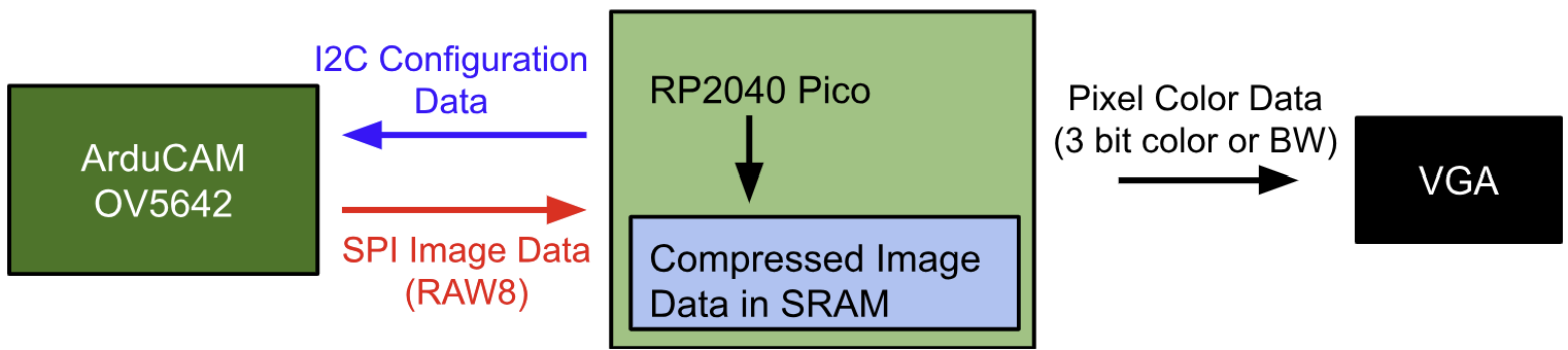
A major hardware/software tradeoff we had to work around was the RP2040's extremely limited memory. The microcontroller has only 264 kB of SRAM memory to work with, which wasn't even enough to store a single black and white image of 640x480 resolution (the resolution of our VGA). Because of this, we had to find a way to significantly compress image data from the camera. Rather than reduce the resolution of the image, we opted to capture only the notable features of the image, such as lines and edges. This way, the image is still decently clear and recognizable, while also taking up significantly less space in memory. Additionally, this has the added benefit of capturing the notable features that may be needed for object detection. Another possible workaround for this memory issue could be to use some form of external memory such as an SD card or external SRAM, but we did not have time or resources to implement this.
ArduCAM has some demo code for the camera for the RP2040, which we used as a starting point [1]. However, there were some major changes we had to make to this code to make it usable for our purposes. The demo merely takes a capture with the camera and sends it to a program on an external computer (via USB) to be displayed. We had to change this so that instead, the image is stored and processed locally on the RP2040 so that it can then be directly drawn on the VGA. This entailed not only getting rid of the USB protocols that were implemented, but also replacing the JPEG format that the demo uses with RAW8. Since JPEG is already compressed, it will be very hard to parse into pixel data, hence why we use RAW8 instead. Additionally, we referenced some code written by an MEng student, Yibo Yang, which implemented a PIO driver for the OV5642 camera to be used with the RP2040 [2]. While this code was not complete, it was a valuable resource to us for understanding how the camera interface works.
Program/Hardware Design
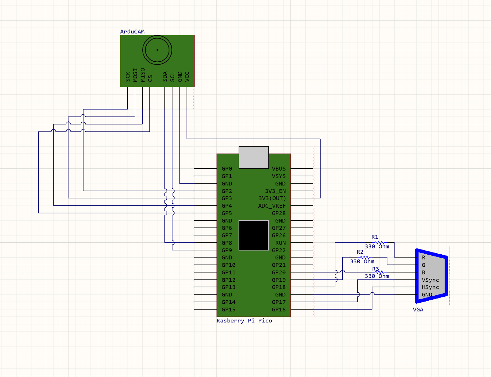
We only had 3 main hardware components that were used in our final project: the Pico, the ArduCAM, and the VGA monitor. We connected the VGA monitor to the Pico the same way we did in Labs 2 and 3, as is shown in the schematic below. The ArduCAM has both SPI and I2C connections to the Pico which is also shown below.
The other code that we used was Professor Adams' VGA graphics driver for the RP2040 and the associated PIO programs. This was used as it was the quickest way for us to get set up with getting visual feedback from the ArduCAM. We also used Bruce Land's protothreads implementation to allow us to have one thread for serial communication to change camera parameters and program functionality and another thread for processing camera information. Other than those programs, we used the Pico C SDK for other functionality like SPI and I2C.
From examining the example code, we decided to write our main project code in C++, as the ArduCAM example code uses a camera object for its functions to control the camera, and we wanted to keep the camera controls to be similar to the examples for the highest chance of working. This decision was tricky at first, as we were attempting to add VGA functionality to the provided C++ code from ArduCAM, but we eventually found out it was easier to start with a VGA demo and changing the file type to C++ (this didn't break the functionality) and then adding the Arducam code to it. We did learn that you have to add an ' extern “C” ' to the includes when the included files are written in C and you are including it in a C++ file.
As for the code's structure itself, we had one thread that was for serial communication over PuTTY and another for the actual camera setup and image capturing. As we did not want our communication over serial to affect the speed of the camera transferring data to the RP2040, we only had the camera's thread yield for 5000usec, as we were willing to have the tradeoff of slow printing and user input so we could have optimal camera performance.
CAMERA THREAD:
The bulk of our coding went into the camera thread, where we handle the setup and communication with the camera, and the processing of data from the camera. This entire part of code took the most work, as the ArduCAM documentation is not very in depth, or completely missing. It took a lot of trial and error, digging through forum posts, and reading the sdk's implementation of functions to get it working.At the start of this function, we reset the Complex Programmable Logic Device (CPLD) of the camera, which is done in the example code, presumably to get the camera into a known state on a new session. Then, we begin to verify the functionality of SPI and I2C. For this camera, I2C is used for changing camera parameters like brightness and contrast, while SPI is the protocol used for the data transfer of the photo information from the camera's buffer where it loads the pixel information. For checking that SPI is functional, we write a number (0x55) to the ArduCAM's test register (ARDUCHIP_TEST1 or 0x00). We then read this value and make sure that it has been changed by this writing, meaning that we have successfully completed a SPI transaction. Then, for checking the I2C communication we read the camera's model number, which is stored in two registers on the camera module over I2C. Once these two steps are finished, we know that the camera is communicating correctly.
The next step of startup is one that took us some time to figure out also, the format of the image. The ArduCAM documentation says that the camera can capture in RGB, RAW, and JPEG. Unfortunately, it does not seem like RGB is fully implemented in the ArduCAM sdk for the OV5640. Because of this, we decided to set the camera's format to RAW, which is the RAW8 image format. This image format has 2 bitx for red, 2 bits for blue, and 4 bits for green. We tried for a while to get RGB working, but it probably would have needed a significant amount of changing the sdk to get working.
We then enter the capture loop, which continuously happens for the rest of the program. At the start of each capture, we flush the fifo, meaning the camera clears out the buffer that the previous image (if there is one) is stored in. We then clear the fifo flag which appears when a capture is complete, and then command the camera to start taking an image. Next, we wait until the camera's bit that corresponds to a completed capture is nonzero. Then, for image processing, we can read the length of the buffer to memory, which corresponds to a 640x480 image.
Then, reading the data from the ArduCAM's buffer was probably the most challenging step of this process. We want to read from the fifo where the image data is stored, so we decided to do that with the ArduCAM's sdk function read_fifo. This initially didn't work, so looking into the function, we saw that it calls buss_read with the single fifo read address as the target register. Then, looking at bus_read's implementation, we were able to see that the code was there for an SPI transaction to take place, but was commented out. Once we added a SPI read to take place there, we were able to get the data for pixels out of the camera's buffer one at a time. From this point on per capture, we are able to read in data from the camera about the image, and do different actions with that data. The following are what we implemented, in the order that we implemented them and in increasing complexity:
Relay directly to VGA:
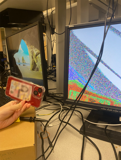
The simplest action that we took as soon as we were able to get pixel information was to send these individual pixels to the VGA screen directly through the RP2040, only processing the colors. We would loop through the length of the buffer on the camera, and for each pixel, we would do a SPI transaction to get the RAW8 information for that pixel. With this, we would have to manipulate the RAW8 data to get one bit per color, as our VGA driver only has support for 3-bit color. We did this by shifting the pixel information until we only had that color's information, and then picked the most significant bit of each of those 2-bit values. Then, we would draw that individual pixel to the screen, and move on to the next. From this, we were able to get images that had color information, and looks like as follows: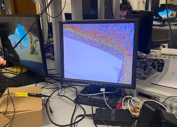
Black and white:
Being able to take images, we wanted to start to work towards being able to store information onto the RP2040, as just forwarding the pixel information to the VGA screen doesn't allow for any real use cases of the camera. Starting off, we needed a way to identify where edges in an image are. To do this, we began by noticing that around edges of objects in our color images, that there were areas of black pixels: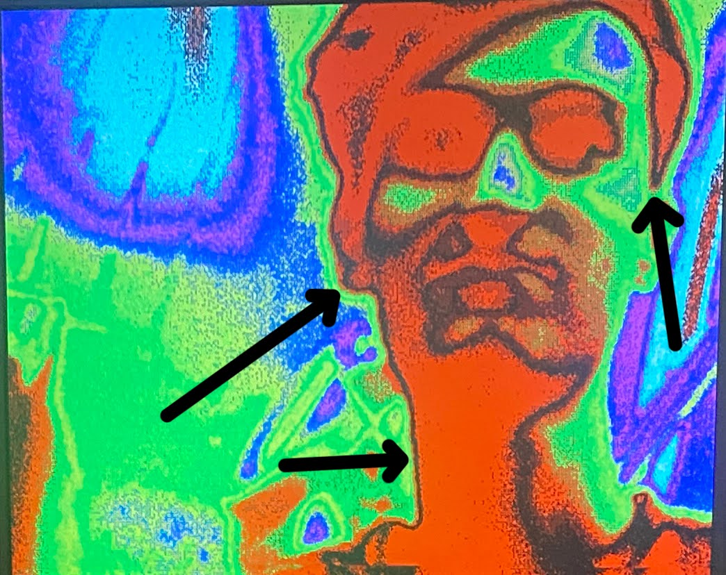
Simple edge detection:
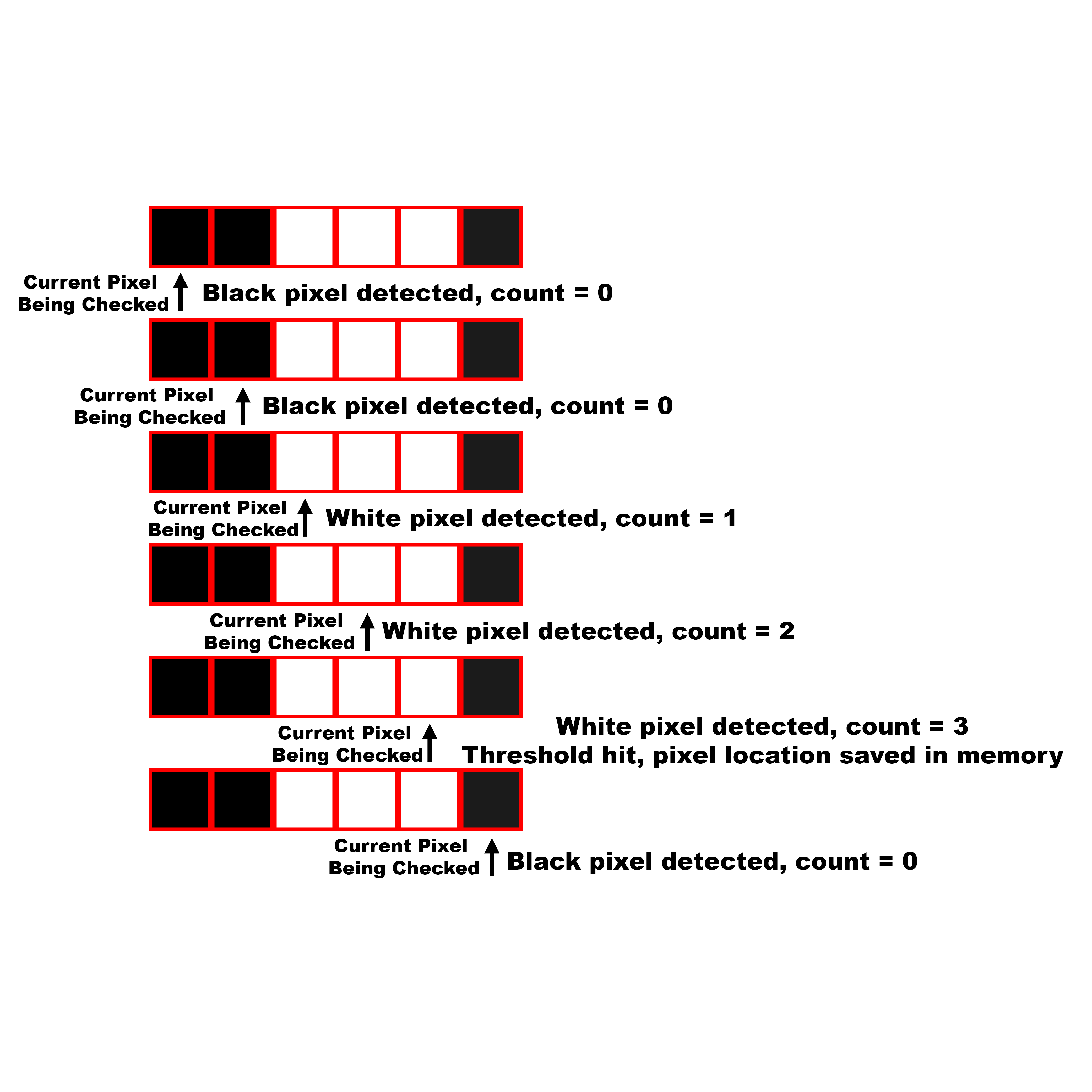
With the knowledge of where these “edges” were in an image, we wanted to be able to save their locations onto the RP2040, as this would make the camera's information useful and could be used for computer vision applications. The hard part of this was being able to fit the image into memory on the processor. The RP2040 has 264KB of internal RAM, so when we save the pixel locations of an edge as a 2D array of shorts representing the x and y coordinates of a pixel, we can only have ~22,000 locations, or ~7% of the screen. This is why we cannot save every pixel that was set as white in the previous section, it wouldn't fit. Because of this, we had to create an algorithm to determine if a pixel is worth saving into memory.Our simple implementation of this was to check the previous pixels in a row, and count how many pixels in a row were detected as an edge using the black and white technique. We were able to adjust this number using our consecutive_threshold variable, that set how many pixels in a row were needed for a pixel's position to be saved:
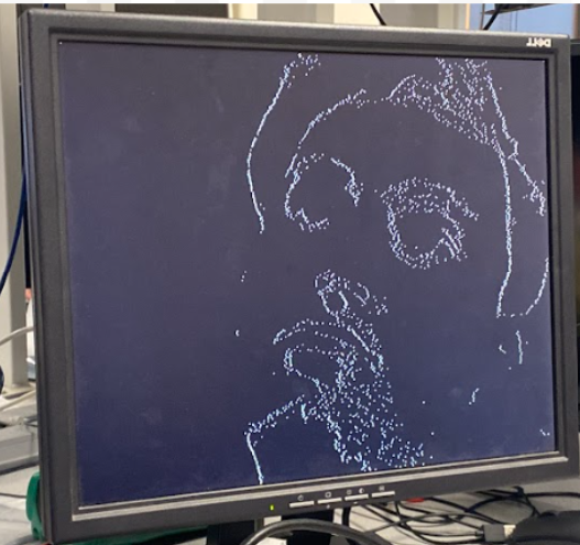
Detailed edge detection:
For our final algorithm, we decided to give it more information to work with when determining if a pixel should be saved. To do this, we had to allocate some space so that we could save previous rows, and then look back at them when we determined if we should save a pixel. We decided to save the previous 3 rows of black and white pixels, and then when we finished reading in 3 rows worth of information from the camera, we would go back through the middle row and check for if an edge was present at each pixel. To check, we would look at the other 8 pixels around this pixel, and if consecutive_threshold (we reused this variable from the simple algorithm) of those pixels were white, we would save that pixel location as an edge location: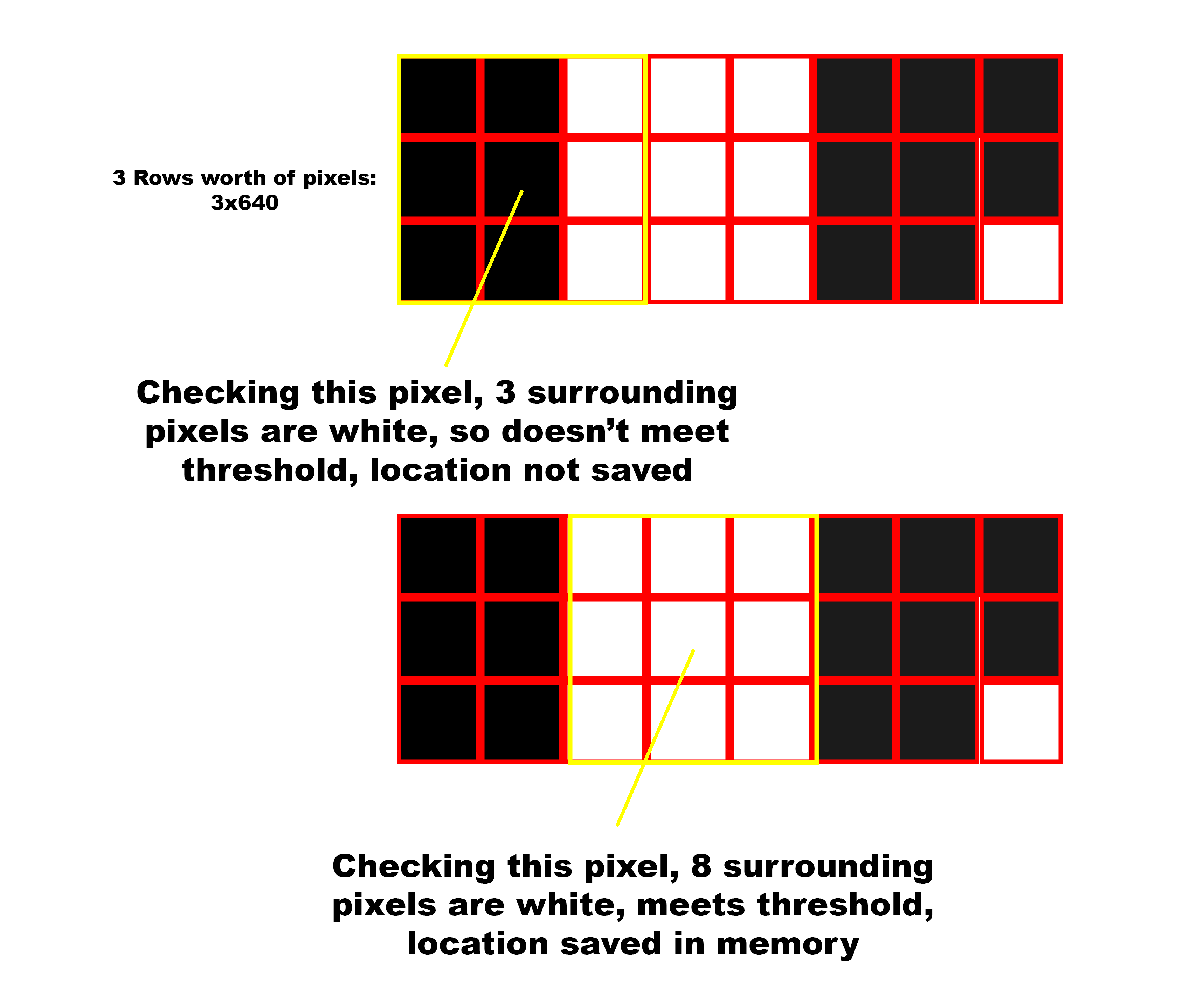
SERIAL THREAD:
Inside of the serial thread, we allowed for a user to change the camera's settings through the provided commands in the ArduCAM sdk. We decided to allow for the user to change contrast, brightness, mirroring, light settings, and toggle test patterns. There were a few other settings that the sdk allows the user to change about the camera (special effects, hue, exposure, sharpness) but we decided that the ones that we allowed to be changed were the best ones for our use case. The rest of the commands in the serial thread are for changing the way that we handle the data coming in from the camera on the RP2040. The commands are as follows:'r': Show the raw image coming in from the ArduCAM directly to the VGA, either in black and white or color (determined by 'm' command). Only processing is color to be showed on screen
'm': Toggle color mode on VGA, between black & white and color
's': Enable simple edge detection
'e': Enable detailed edge detection
'd': Adjust amount of dithering for edge detection. This will set a number of the minimum number of pixels between pixels saved in memory when saving edges to save on memory
'n': Adjust the threshold for edge detection, meaning that it changes the number of pixels each check for if we should save a pixel (edge) in memory. This changes the threshold for both simple and detailed edge detection.
Results
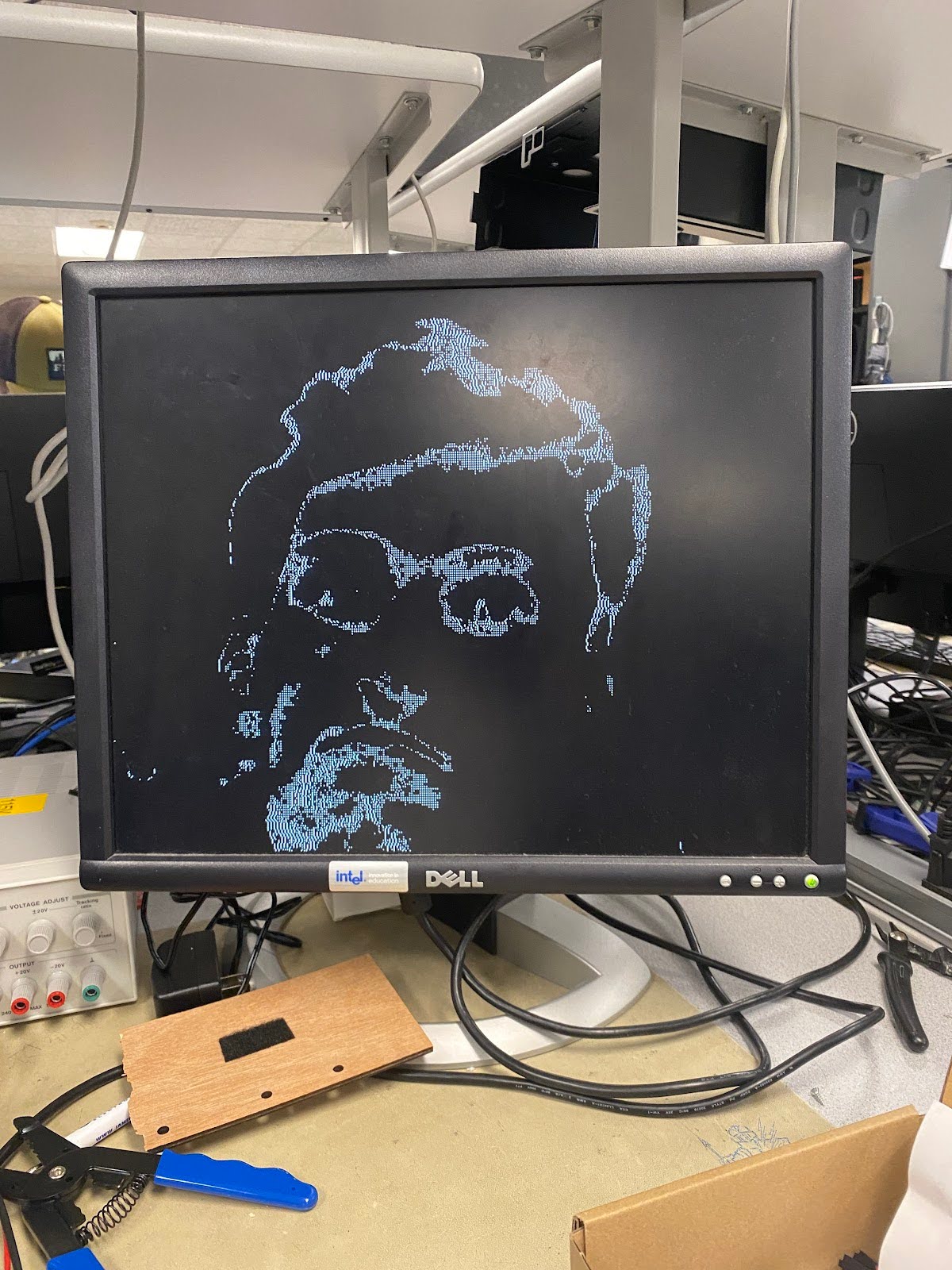
Our end result was both baseline code for connecting the Raspberry Pi Pico to a camera and a working edge detection algorithm. Given the nature of the project the results are very visually-based, so we'll walk through some of the images we have.
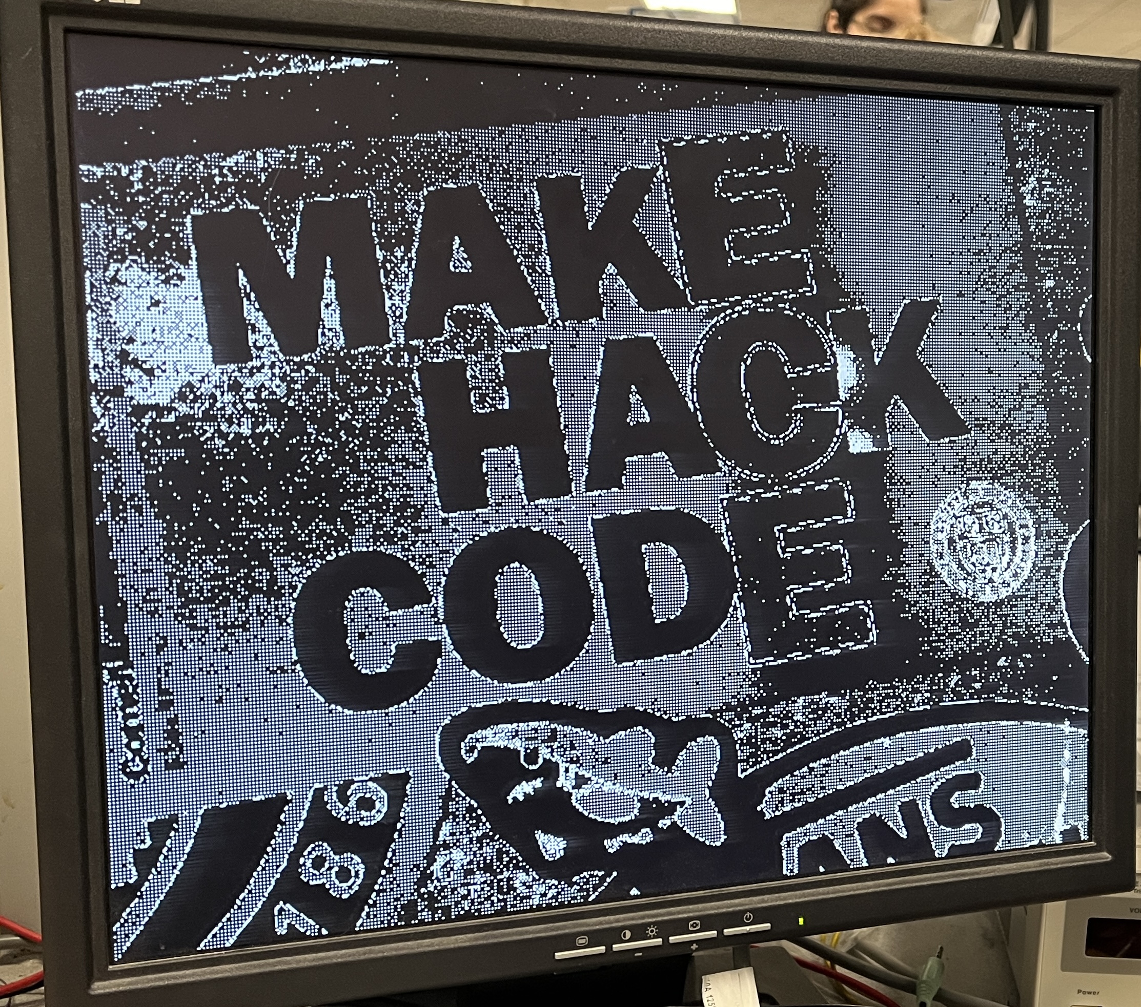
Pictured below is one of the first images we generated with the camera with recognizable details. Although the colors aren't correct, which we'll remark on later, the shapes can be made out.
Conclusions
In the end, we're very happy with the results from our project. One thing that we didn't expect was how long it would take to actually get the camera working with basic functionality. Our original goal for the project was eye tracking, but we quickly adjusted after seeing the difficulty. That being said, future groups can use our code as a starting point and build some sort of eye tracking algorithm from there.
If we were to do this project again there are a few things we would change. The first of these is to try to further integrate the VGA driver into the camera program. This would allow the VGA array to be written directly from the camera to save pixel data that is to be processed. Additionally, a 4-bit color VGA driver would allow for color accuracy, as the RAW8 file format we currently use has proved difficult. Another change we could make would be implementing external memory, which could allow us to do more in depth image processing as we could save more data per frame. Finally, if we had more time we would have spent more time focusing on how to correctly represent colors. This would involve focusing more on the data we are receiving and implementing a correct conversion for our VGA driver.
As for intellectual property considerations, we did use code in the public domain, which was provided by ArduCAM. This is mostly example code that we had to make changes to so that it would run properly for our implementation. Overall, our group was able to get a working edge detection program interfaced with the Raspberry Pi Pico.
Appendices
Appendix A (permissions)
"The group approves this report for inclusion on the course website."
"The group approves the video for inclusion on the course youtube channel."
Appendix B (code)
Github Link: https://github.coecis.cornell.edu/gjt29/ECE4760-ArduCAM-OV5642-Public
Most of the code we worked on is in cam_vga/2040camera.cpp
Appendix C (Work Division)
Hardware/Code/Testing: Noah, Jason, Grace
Report:
Intro and high level design: Grace
Program/hardware design: Jason
Results/conclusion: Noah
Appendix D (references)
[1] Arducam 5MP Plus OV5642 Mini Module Camera Shield SPI camera module for Arduino Uno MEGA2560 Board & Raspberry Pi Pico. Arducam. (2023, May 7). https://www.arducam.com/product/arducam-5mp-plus-spi-cam-arduino-ov5642/
Software Documentation: https://www.arducam.com/downloads/shields/ArduCAM_Camera_Shield_Software_Application_Note.pdf
Code: https://github.com/ArduCAM/PICO_SPI_CAM/tree/master
Tutorial: https://docs.arducam.com/Arduino-SPI-camera/Legacy-SPI-camera/Pico/Camera-Module/SPI-Camera/
[2] Yang, Y. (n.d.). DESIGNING A CAMERA MODULE DRIVER USING PROGRAMMABLE I/O ON PI PICO RP2040. School of Electrical and Computer Engineering of Cornell University. (2022, Dec.) https://vanhunteradams.com/6930/Yibo_Yang.pdf
Code: https://github.com/thomasyyb/PiPico/tree/master