Our final project demonstrated the display of RGB565 16-bit color (also called high color) over VGA using a Raspberry Pi Pico. To the authors’ knowledge, this is the first ever implementation of RGB565 on a Pico above 320x240 resolution without the use of an SPI display with a built-in frame buffer. In other words, our display driver stores the entire frame buffer in SRAM onboard the Pico, and our monitor does not buffer any pixel data written to it. Importantly, our adapter can interface directly with any commercially available VGA display without any additional proprietary hardware.
Various optimizations and configurations were required, both from hardware and software, to conform to the strict hardware requirements of the Pico.
Our inspiration for this project came from a video made by YouTuber “Ben Eater” titled “The world’s worst video card?” (Video link: https://youtu.be/l7rce6IQDWs?si=WuT67nbaP6HmP-60). In this series, Eater built a functional VGA display adapter exclusively from analog and TTL components including shift registers, adders, binary counters, and EEPROM. Although the adapter was very basic, capable of only displaying a maximum of 64 colors at a resolution of 100x75 pixels, it was still a significant achievement in the breadboard computer community. We sought to expand on this and similar projects to build a video display adapter but with much more capability.
While defining our project scope, we researched two prior groups from Cornell who had attempted similar VGA display adapters to our own.
The final design was an RGB565 VGA-compatible display interface with an output resolution of 400x300 pixels. Two PIO state machines onboard the Pico were chained to DMA channels responsible for pushing color data out of 16 GPIO pins, one per color bit. Two additional state machines were used to generate the H-sync and V-sync video timing signals required by the VGA specification. Additionally, an asynchronous communication standard was added on top of a generic UART channel to allow us to design programs on other platforms to control our VGA display adapter. For example, we modified an open source ray tracing library to run on a laptop and wrapped the library in a UART application to allow the laptop to send the individual pixel values to the VGA adapter, so that we could visualize the ray-traced scene in real-time.
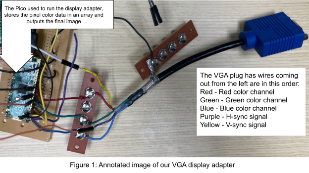
The primary piece of hardware used was a single Raspberry Pi Pico microcontroller. The Pico contained a dual-core RP2040 microprocessor which we overclocked to 270 MHz, and also packaged 264 KB of onboard SRAM. The Pico was responsible for the timing of a valid VGA signal. Figure 1 below is an annotated image of our display adapter which shows the Pico and the wires which connect the Pico to a VGA plug, which can be connected to a monitor.
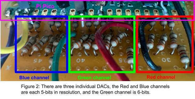
The second piece of hardware was a set of digital-to-analog converters (DAC) built using resistors. We soldered together a R-2R ladder, which is a DAC built exclusively from resistors of resistance R (in this case, 330 Ω) and 2R (in this case, 680 Ω) because if the resistors are cherry-picked such that each resistor’s resistance is close to the required R or 2R rating, then this type of DAC is much more accurate than a binary weighted resistor DAC. Three DACs were constructed, one per color. Because our target color space was 16-bit, also called RGB 565, a 5-bit DAC was used for the red channel, a 6-bit DAC for the green channel, and a 5-bit DAC for the blue channel. Figure 2 below is an annotated image of our DACs.
We note that although 680 Ω is not an exact doubling of the resistance of 330 Ω, we specifically cherry-picked our resistors to be close to an exact doubling. For example, in the red channel DAC, 5% tolerance resistors were selected from a large 330 Ω bin to be close to 335 Ω, and 5% tolerance resistors were selected from a large 680 Ω bin to be close to 670 Ω. Below is a table of our selected resistors, and their total tolerances from each other.
Red Channel | Green Channel | Blue Channel | |||
R: 335.7 Ω, 335.2 Ω, 335.8 Ω, 335.0 Ω | 2R: 671.0 Ω, 670.8 Ω, 671.2 Ω, 671.0 Ω, 670.4 Ω, 670.5 Ω | R: 333.4 Ω, 333.2 Ω, 333.8 Ω, 333.0 Ω 333.0 Ω | 2R: 667.0 Ω, 666.8 Ω, 666.7 Ω, 667.2 Ω, 667.0 Ω, 666.4 Ω, 666.6 Ω | R: 334.2 Ω, 334.2 Ω, 334.3 Ω, 334.7 Ω | 2R: 667.8 Ω, 668.8 Ω, 668.2 Ω, 668.0 Ω, 668.1 Ω, 668.7 Ω |
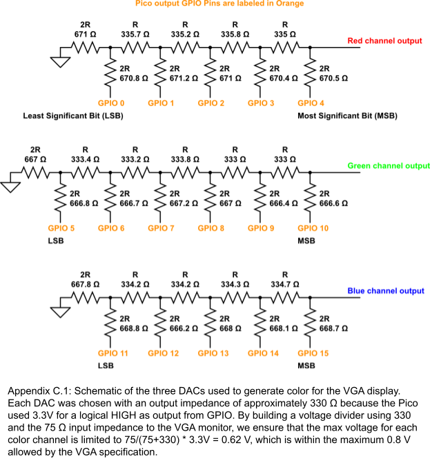
The DACs were each soldered to the Pico through perfboard. We could not use a solderless breadboard because the frequencies required for our circuit were over 30 MHz, and the breadboards available had too high of parasitic capacitances to support those high frequencies. A detailed schematic of our DAC design can be found in Appendix C of this page.
To demonstrate the Pico’s ability to display 16-bit color, our program allowed for the display of both dynamic and static images. A UART communication channel was established to allow for external sources (in our case, either another Pico or a laptop) to push an image frame to the Pico VGA adapter for display. Additionally, six 400x300 resolution images were loaded into the 2MB of onboard flash, and could be cycled and shown to the display via a push button. To introduce as little memory overhead as possible, the unsigned short data type (which has a range of 16 bits, equivalent to the 16-bit color range) was used to store a single pixel’s color value.
The majority of the project was spent on interfacing the Pico with a VGA display by optimizing our VGA driver for high-speed GPIO connectivity. But first, we would like to explain more about the VGA specification and how we realized the complex timing scheme in code.
We dissected van Adams and Land’s codebase for 8-bit color at 320x240 pixel resolutions. According to TinyVGA, a 320x240 resolution could be achieved by “downsampling” a standard 640x480 resolution signal in half by both the horizontal (called a scanline) and vertical (called a frame) directions. In other words, by sending the same color value twice for every pixel in a scanline, and by duplicating each scanline twice, a monitor is essentially displaying a 320x240 color image while operating at a higher 640x480 resolution. This process is known as pixel doubling or scanline duplication.
The 400x300 resolution could be achieved with a similar doubling procedure from the native 800x600 resolution. According to TinyVGA, the 800x600 timing standard utilized a 36 MHz pixel clock. This was the frequency used to send a single color pixel to the display. Additionally, the VGA signal itself was broken down into a few portions. For example in each scanline, the first 24 pixels drawn (the front porch) are not shown on screen, but the subsequent 800 pixels create the width of the visible area of the display. Next, 128 pixels are drawn off-screen (the back porch) and then a final 72 pixel “H-sync” pulse is initiated. During the sync pulse, the voltage of the color lines and the pulse itself must be shorted to ground. This gives the display time to “sync-up” the pixel drawing signal with the display, and also gives the display time to erase (blank) the screen. A similar sequence of front porch, visible area, back porch, and V-sync pulse is performed in the vertical direction. But because VGA scans lines from top to bottom, the V-sync pulse only needs to initiate at the end of every frame.
Therefore, the software design theory was to write a simple loop to trigger once per tick of a 36 MHz clock. Upon receiving the trigger, the loop would index into a large array containing every pixel value for the display and get the value of a 16-bit integer. It would interpret the integer as 16 binary digits and output the integer along 16 GPIO pins for color, one pin per digit. Additionally, another clock would generate the H-sync and V-sync pulses, and a loop would trigger every time the H-sync and V-sync signals should be grounded. At this time, the binary value “0” was written to all 16 GPIO color pins, and held until the pulse ended. Then, the binary values for the next color would be written to the color pins. Additionally, to perform scanline duplication, another loop or flag would control if the previous scanline had been duplicated. If the flag was not set, then the last scanline had not been duplicated, so duplicate the last scanline and set the flag. Otherwise, the last scanline was duplicated, so move on to the next scanline and reset the flag. Below, we present some pseudo code which exemplifies the desired behavior.
DEFINE 36 MHz and H/V-sync clocks DEFINE VGA pixel color data array DEFINE flag LOOP FOR EACH 36 MHZ tick: Index into VGA data array to obtain 16-bit integer Output each binary digit in the integer as one of 16 GPIO pins for color LOOP when H/V-sync should be grounded: Write "0" to all 16 GPIO color pins Hold this value until the pulse ends Write binary values for the next color to the color pins LOOP FOR EACH scanline: If NOT flag: draw last scanline # duplicates the last scanline set flag If flag: draw next scanline reset the flag |
Finally, the reader may be curious as to why it was necessary to “trick” the monitor into receiving a signal at 800x600. Why could we not send a raw VGA signal at 400x300 resolution? Simply put, there is no official display standard at this resolution. The smallest VGA resolution standardized by IBM was 640x480, and by the Video Electronics Standards Association (VESA) was 800x600. Historically, displaying resolutions smaller than this were either handled with proprietary protocols or with scanline duplication, which is the method we used.
Firstly, we needed a way to store the color value for each pixel on the screen. As described in the Software Design introduction, we initialize an array of size 120000 with the unsigned short data type to create an array with enough space to hold a 400x300 frame buffer. This frame buffer consumed 240 KB, which fit snugly into the Pico’s 264 KB of SRAM.
Next, we realized the concept of loops, but at a fast speed. The Pico’s onboard processor is slow and cannot move data from SRAM to GPIO fast enough to support the resolution and color space demanded by our display. We were inspired by van Adams and Land’s design using PIO state machines and DMA to quickly move VGA pixel color data from SRAM to output ports. A PIO is essentially a self-contained computer within the Pico. It can execute its own machine code written in PIO assembly language, and can interact with memory and peripherals much faster than the Pico itself. Van Adams and Land’s design efficiently uses PIO to generate the pixel clock, H-sync, and V-sync display signals, then chains multiple DMA channels to the sync signals so that when they are pulled high during the active period, the DMA channels directly move pixel color data from memory to peripheral GPIO, and when the signals go low during blanking, the DMA channels push a binary “0” out to peripheral GPIO, enforcing the VGA specification. Therefore, to achieve 400x300 we had to first alter the timing specifications.
One caveat we constantly considered was the limited number of instructions available on the PIO state machines. Due to hardware limitations, each PIO on the Pico is limited to 32 instructions shared between 4 independent state machines. Although busy waits (no operation, NOP) could be performed for a short period after each instruction without incurring extra lines, we had to be very selective and efficient throughout the development of our PIO driver.
To generate the 36 MHz pixel clock, we first overclocked the Pico to 270 MHz over the stock 125 MHz. Luckily, the Pico SDK exposes a system call set_sys_clock_khz() which automatically attempts to set the Pico to a desired clock speed, in kilohertz. Next, we used a PIO state machine and a clock divider of 7.5 to operate the state machine at 270/7.5 = 36 MHz. The rgb and rgb2 state machines pushed color values out to the display in 16-bit chunks, where each chunk represented one pixel’s color value. They were each triggered by the H-sync signal (an interrupt we will later describe.) The purpose of using two separate color state machines was to enforce the synchronization and duplication of scanlines. In other words, rgb drew the first scanline, then rgb2 drew the duplicated scanline. This system gave us accurate, time-determinate control over the scanlines and removed extraneous logic and instruction overhead. Each state machine consumed 5 instructions, totalling 10 instructions for our color display logic.
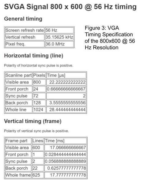
To generate the H-sync and V-sync pulses, we again utilized PIO state machines, but divided a 270 MHz clock by 90 to operate a H-sync PIO at 3 MHz, and blocked the V-sync pulse from triggering until after 300 H-sync pulses. Equivalently, these timings satisfy the 800x600 VGA timing specification at a refresh rate of 56 Hz. Figure 3 below from TinyVGA details the timing and pixel clock for the 800x600 @ 56 Hz specification.
The H-sync and V-sync pulses are responsible for making sure the display renders the correct pixels in the correct order at the correct time. While it is true that timings do not necessarily need to be exact (for example, our own timing is actually out of spec from the true values by up to 6 percent), they need to be very close or else the displayed image may look distorted. The reason we settled for a 3 MHz clock speed for the H-sync PIO is because a 3 MHz frequency is equivalent to a 0.333 µs cycle time. Looking at the specification, we can see that the duration of the front porch and sync pulse can be divided cleanly using integer values into 0.333 (0.667 divides into 2 and 2 divides into 6) while the back porch and visible area values are relatively close (3.333 vs 3.555 divides by 10 and 22.333 vs 22.222 divides by 67), so the final timings are close to the expected values. Again, we do not need to worry about V-sync timing parameters because we chained the V-sync pulse to block for 300 H-sync pulses, so as long as the H-sync pulse is triggered with accurate timing, then the V-sync pulse will be accurate as well.
There existed a tradeoff between super accurate timing and PIO instructions consumed. For example, the reader may realize that choosing a clock speed of 9 MHz and a cycle time of 0.111 µs will yield timing values which are all integer divisible. But at this higher clock cycle, we need to delay for a longer time because each instruction also takes a shorter time to execute. Logically, this is equivalent to saying that if it previously took 67 instruction cycles to busy wait 22 µs, then now it would take 67*3 = 201 instruction cycles to busy wait the same 22 µs. Because we were heavily limited on instruction count, and each instruction was limited to a maximum busy wait time of 32 cycles, then we could not afford to incur additional instructions for more accurate timing. Luckily, real-world engineers have already thought of this potential problem, and VGA monitors now come with an “auto-adjust” feature that adjusts the display’s internal clock to match up with input signals which are close but not necessarily following the VGA specification exactly. This way, beautiful images can be displayed even from signals which drift slightly.
During the development of this driver, we exploited a unique feature limited to resolutions at 800x600 and resolution which was the driving reason why this project was feasible. Namely, at the native 640x480 resolution van Adams and Land referenced, the specification called for a 10 line delay for the V-sync front porch. This delay was realized through a counter and a loop, where a scratch register was initialized to 10 and decremented upon each H-sync scanline, branching upon a JZ (jump if zero) statement. Such a loop, however, took four instructions. At this point, we had already used 30 instructions total for both of the color machines, H-sync, and V-sync machines, and so an additional four instructions would no longer fit inside the PIO. However, at the 800x600 resolution, no loop is required because the specification only called for a single front porch line. Therefore, a loop was redundant because a single wait instruction triggered by a single H-sync scanline resulted in identical logic. We saved 3 instructions and managed to fit the new logic into our PIO.
A final constraint to the color PIO was the grounding specification. During blanking at the end of every scanline, we needed to ground all 16 color pins, which could be done by sending the binary immediate value “0” to each pin. Again due to hardware limitations, the Pico only supports setting an immediate value to a maximum of 5 pins. Troubleshooting this bug was problematic because we were unsure why Raspberry Pi only allowed five pins to be set using an immediate value, when other methods allowed as many as 32 pins to be set. Regardless, the symptom of this bug was that the display only showed shades of red. This made sense because the five least significant bits of a 16-bit color value corresponded to the red channel on our DAC, which prevented other colors from being properly blanked. We solved this problem in software later by forcing all images drawn to the Pico to contain a black pixel at the 400th pixel in a scanline. By doing so, we trick the display into believing that the color pins are grounded during blanking. Of course, this means that our monitor’s resolution lowered from 400x300 to 399x300, but it also enabled all 65,000+ colors.
In summary, our driver utilized a single PIO block and all four state machines, consuming 31 of a possible 32 instructions. We believe that this is the most efficient implementation of a VGA driver using PIO on a Pico thus far.
Direct Memory Access (DMA) is a technique to accelerate the transfer of data from memory to peripheral devices. It does not consume precious CPU cycles, thereby moving the critical path away from processor overhead and allowing the Pico to achieve data throughput of over 133 MB/s. Our driver uses DMA to move color pixel data from the pixel color array in SRAM to the PIO state machines for display. A total of four DMA channels were used, two per RGB color PIO state machine. In each RGB color state machine, the first DMA channel copied an entire scanline to the read buffer of the PIO state machine using a pointer to the pixel color array, and the second DMA channel increment the pointer to the color array by one scanline, which reconfigured the first DMA channel to be ready to copy a new scanline from the color array to the read buffer. The DMA channels are also paced by the current state of the read buffer of the PIO state machine. In other words, the DMA channels will only begin a data transfer if the read buffer of the state machine is empty. If the buffer is filled, then DMA will block until the buffer is empty again. This way, the DMA never overwrites any contents already waiting to be displayed to the screen.
Leveraging the 2 MB of flash memory onboard the Raspberry Pi Pico, we stored six test images each with a resolution of 400x300. This was a strategic use of memory, as each image occupied approximately 240 KB of the available flash memory. We were unable to fit additional images because the entire loadable executable was over 2036 KB, just 12 KB below the maximum which could be programmed onto the Pico. We chose images which were vividly colored to best test our hardware and software capabilities.
Each image was stored as a header file which declared a single unsigned short array. Each element in the array represented the color of a single pixel. The type declaration of each image was const unsigned short __in_flash() image_arr[120000], with the __in_flash() definition telling the compiler to allocate memory for the image in the memory-mapped address space for flash memory.
To facilitate user interaction, we configured a button linked to GPIO pin 26 where a button press switched to the next image. This setup was enhanced with debouncing, ensuring a stable single-step transition between images. Upon pressing the button, a DMA channel was configured with a pointer to the start of the selected image's array in flash memory, enabling quick and efficient display changes without corruption.
A key aspect of our project was to showcase the Pico's capability in running visually demanding programs and outputting 16-bit color on a VGA display. Our approach focused on adapting and optimizing existing compute-intensive visual programs for the RP2040 chip. A prime example was the implementation of a ray tracer algorithm to generate and load images onto the Pico dynamically via the UART communication protocol. We adapted and improved the Ray Tracing algorithm from the open-source Ray Tracing in One Weekend GitHub repository. Though the Pico is capable of running this algorithm, the time-intensive nature of image generation – approximately a day for a full image – led us to run the ray tracer on a Windows computer for the demonstration.
During development, significant efforts were made to optimize the rendering process. The ray tracer was parallelized across 20 threads, each handling the generation of 15 rows of pixels (300 total rows divided by 20 threads). Additionally, C++ double types were replaced by floats. In total, these changes sped up rendering by over 8x versus the stock renderer. On the display adapter, we used the Pico’s second core to asynchronously accept data over the UART, which is non-blocking and independent from our image display PIO and DMA channels. Upon startup of the Pico, the core independently initializes a UART connection using GPIO pins 21 and 22, then waits for incoming UART data. Pixel data from an external source, no matter whether it be from a laptop or another Pico, was sent line by line in the form "[line number]:[color 1]:[color 2]:…". This colon-delimited scheme enabled us to use a buffer and the C scanf() library function to tokenize and write the incoming pixel data directly to memory.
One issue we realized early on was that sometimes, the Pico would draw an incomplete scanline to the display and draw random red pixels, seemingly suggesting that our blanking trick had suddenly stopped working. We narrowed down the problem to the fact that the Pico’s slow processing speed meant that it could not keep up with incoming UART data from a powerful laptop running the ray-tracing software. Therefore, we implemented a mutex such that any device attempting to communicate with the Pico over UART had to first lock the mutex before attempting to send pixel data to the Pico, and could only unlock the mutex after the Pico was done writing the entire scanline to the screen. We also considered the effects of messages dropping out due to loose connectors, and came up with a synchronous handshake protocol with message repetition. For example, the Pico repeatedly transmits the string done after writing a scanline, which boosted the reliability of our protocol by forcibly retransmitting messages.
The main goal of our system was to create a display interface to render and display 16-bit color images onto a VGA display. Our current system is able to store various images in flash and also load in images as pixel data through UART. Throughout the development process, we found various ways to test the functionality and capability of our system.
Firstly, we verified the precision of our timing using an oscilloscope and VGA monitor. Without any high level UART communication code running, we only configure and enable the H-sync and V-sync PIOs to determine whether our state machines could generate a valid VGA timing. We probed the GPIO output and determined that the H-sync pulse lasted for exactly 2 µs. This perfectly matched our expectations because we used a H-sync PIO clock cycle of 3 MHz, and waiting 6 instruction cycles at this frequency yields an exact 2 µs pulse duration. As a real-world sanity check, we connected our adapter to a Dell branded VGA display, and it was able to detect both our target resolution (800x600) and refresh rate (56 Hz).
We proceeded to test the RGB PIO state machines. We began with displaying a solid color, which worked fine, followed by a vertical gradient of shades of red, green, and blue, which also worked. We then wanted to test our system by displaying more complex gradients to test the entire range of the color palette. It was through this test that we identified the hardware limitation where only five pins could be set using an immediate value, which caused all of our test images to only show red. By replacing the final column of pixels with all black, we solved this bug and the screen could blank successfully, unlocking the full 16-bit color space. Figure 4 below is a test gradient we captured which showcases the excellent color range of our display adapter.
After we were able to test displaying the whole palette, we moved onto displaying test images, both from flash and from external data. Below are the sample images being shown on a real monitor using our display adapter, as evident by the Moire patterns on the display. The images have no color correction applied.
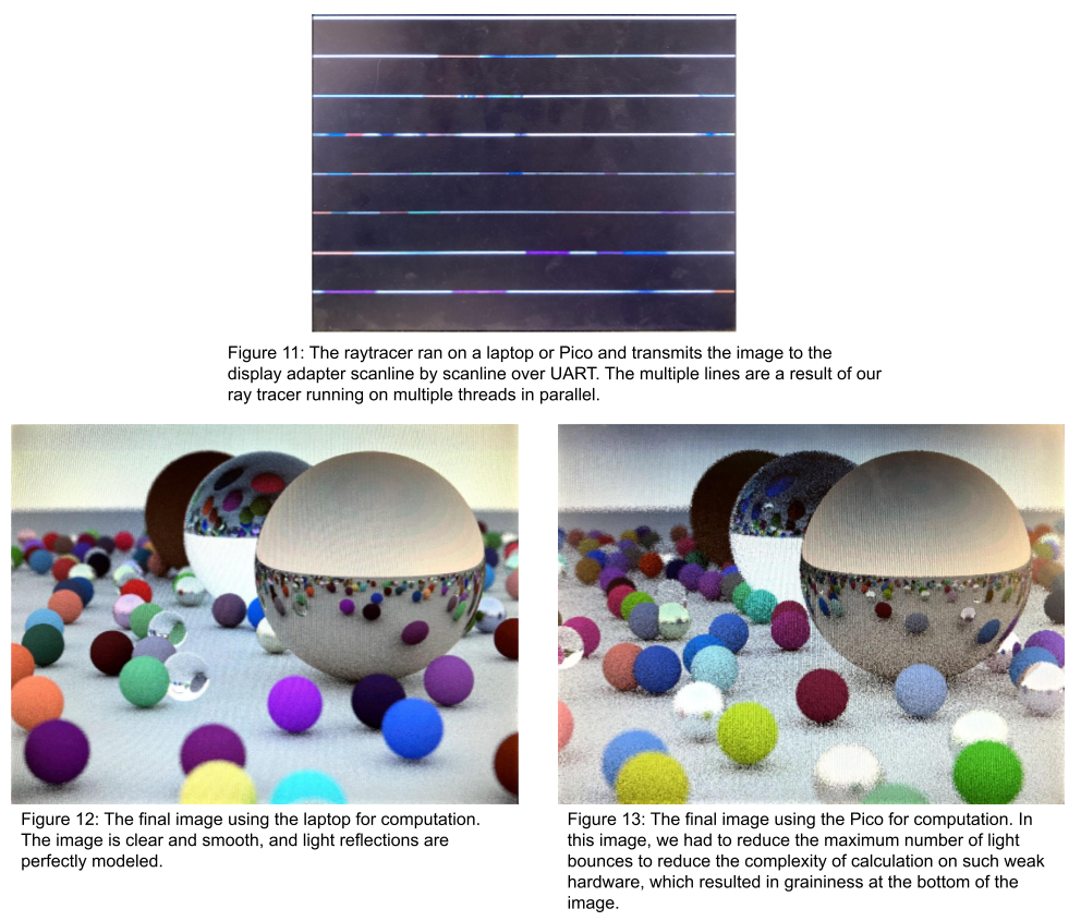
We tested our UART protocol by first opening a terminal UART channel on our laptop and then sending pixel data to the Pico, ensuring that our Pico parsed the pixel data correctly. Figure 11 below shows the raytracer in progress, while Figures 12 and 13 are images captured of the resulting scene. Figure 12 was the computational result from the laptop, and Figure 13 was the result from the Pico. The scenes appear slightly different because the raytracer randomly picks positions and colors for each ball, so the final rendered image has variation.
As an end-user, interfacing with the Pico is seamless. To load an image dynamically, simply open any serial terminal application (like PuTTY) and you can begin sending pixel data to the display. It is possible to send scanlines manually, or in our case, we wrote an application to take care of this for the user. As for static images, switching between different images is as simple as a button press.
Additionally, care was taken to make the end product durable and reliable. We double soldered all joints to ensure that even with heavy abuse, no wires would be bent or broken. Additionally, a VGA plug was salvaged from an old VGA-to-DVI display adapter, and we joined the plug to the H-sync, V-sync, and color channel outputs using terminal blocks. The terminal blocks allow end users to replace the VGA plug, should it ever fail. Also, terminal blocks ensure a tight, secure connection which will not degrade over time.
In our program, we have pixel data that is sent over by UART by multiple threads and also two cores in the Pico to display images. To endure that no data is lost, we use concurrency techniques in order for safety. We first use a mutex and handshake protocol among different threads when sending data through the UART. When a thread is able to take the mutex, it takes it and sends data over UART, preventing other threads from writing to UART. The thread holds the mutex until the Pico sends a "Done" signal to show that the Pico has finished sending the line to the data array, meaning that it is in the VGA display. This mutex prevents other threads from trying to write data to the Pico when it is not ready, leading to the new lines being discarded and ignored. The image in the process of being rendered is shown in Figure 9.
To prevent deadlock between switching static images and waiting for the UART communication, we separate the two processes between two different cores so that they act independently. Thus, the static image has no effect on the ray tracer image generation and vice versa. However, one bug that comes with this is that when we want to switch the static image while we are sending data over UART, the old pixel data to display on the VGA is wiped, and the UART data being sent overwrites the new static image, with only the new pixels sent after the image switch staying on the VGA.
The main system optimizations were done on pre-existing ray tracer code in order to make it faster. Originally, we wanted to run the ray tracer on a second Pico, but that took an entire day to render. Bringing it to the laptop reduced the running time to 5-10 minutes, depending on the laptop used. In addition to multithreading described in the previous section, which reduced rendering time by 500%, we applied further optimizations. These included bit-width reduction by using floats instead of doubles, which contributed a 5% reduction in render time, and setting the compiler to the -O2 optimization flag, resulting in an additional 30% render time reduction. The combination of these optimizations reduced render time so significantly that UART communication was the primary bottleneck in displaying the image. With these optimization techniques, the image generation time was around one minute.
We were able to construct a two part system: first having the ability to render 16-bit high color on a VGA display using 400x300 @ 56 Hz resolution and second modifying pre-existing ray tracer code to be more efficient and communicate with our Raspberry Pi Pico. Even though we have achieved a complete system, this was not our original plan. We originally had a second Raspberry Pi Pico which would run the ray tracing algorithm, but as we described earlier, it would take too long, taking a day to render. We also wanted to be able to display a native 800x600 pixel display using external SRAM to hold the large 1 MB frame buffer needed at this high resolution. But during the process, we fried the RAM chip. Despite this, our system was able to fulfill the overall functionality we wanted for the project, especially using 16-bit color.
Through this project, we also had to use various standards which interface with our Raspberry Pi Pico. The first was the UART communication protocol standard, which dictates the baud rate we need to use to transfer data to the Pico. The second was the VGA standard. The VGA standard sets the required timings necessary for the HSync and VSync signals and we used that standard to get our image to display properly.
To aid us, we in addition used two sources of code which helped with the implementation of the project. The first was the code Professor van Adams and Professor Land used for their 8-bit color implementation. This helped us greatly in figuring out how to set the PIO state machines and DMA channels for 16-bit color. The code we used was used with permission from the two professors. The other code we used with the base for the ray tracer algorithm, which comes from an Open Source Github repository called Ray Tracing In One Weekend. As it was open source under the CC0-1.0 license, the code is in the public domain and we are able to use it for our needs. Overall, this project has been very fun and fascinating for the whole team and it was very enjoyable.
The group approves this report for inclusion on the course website.
The group approves the video for inclusion on the course Youtube channel.
The group published all source code to GitHub, the public repository is visible here: https://github.com/bublyapplejuice2/RP2040_16bit_VGAdriver
Appendix C.2: Bill of Materials
2x Raspberry Pi Pico RP2040 | $8 |
Mixed 330 Ω and 680 Ω resistors | $10 |
Salvaged VGA plug | Free |
Miscellaneous wires and connectors | Free |
Total Cost: $18 |
Howard Hua: Soldered the DAC together and connected the Pico to the DAC, programmed all PIO state machines and DMA channel configurations. Soldered a VGA plug to the final project to aid in ease-of-use.
Michael Wei: Ported the ray tracer application to the Pico, optimized the ray tracer using multithreading and low-level functions, built a UART communication application to connect the Pico to a laptop or separate Pico.
Peter Cao: Debugged the PIO state machines and UART communication application to the Pico.