Hardware and Software Design

Hardware Design
From a hardware perspective, the project was very involved. All electronic components revolve around the RP2040, used to analyze user inputs and various data and to send commands to both LEDs and audio speakers as response to such data. The whole project can be divided into sections, which we will cover independently, each covering a specific functionality of the whole machine. One fundamental feature of our project is that it is almost entirely autonomous and independent. It is in fact powered by batteries so it can be transported anywhere without the necessity to be connected to a computer, with the only exception being the speakers which need to be powered to an outlet to function. Our system, although big in size, can be treated as a portable self-sustained machine.
Resistor Lamp and Physical Setup
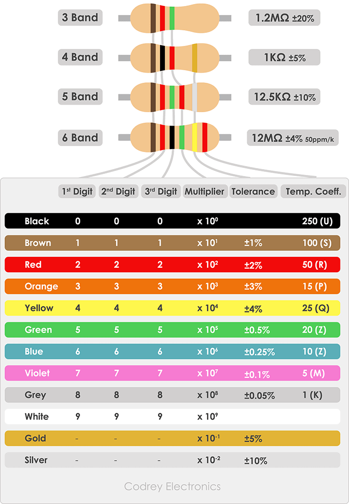
The entire system is housed on a large rectangular wooden board. There are three “legs” on the bottom side of the board so that the breadboard that is hidden underneath would be suspended in the air. The frame of the resistor lamp is made out of two plastic water bottles joined together. There is a strip of 15 LEDs inside the bottle, and it is separated into sections using cut outs of circular black foam. We turned on different LEDs based on the number of bands that were selected. For example, if the user selected Series 3, the colored bands would appear on LEDs 4, 7, and 10. A large paper was wrapped around the inside of the bottles so that the light bands were easier to see. Components like the display, buttons, and lamp were secured to the wooden board using hot glue. Hot glue was a good option because it is easily removable and should not damage the components. We also included decoration LEDs around the border of the wooden board and a table with the meaning of each color of the band. Each strip of LED was connected to a GPIO on the Raspberry Pi Pico that would send the coloring data to the LEDs. The LEDs were powered with 4.5V, from the batteries. The microcontroller was also powered by the batteries using the 3V3_SYS pin.
Voltage Divider
In order to determine the resistance of the inserted resistor, the voltage divider is a critical component. We used a reference resistor with a resistance of 10kΩ. One end of this resistor is connected to 3.3V power and the other leg is connected to an alligator clip that would interface with the inputted resistor. There is another alligator clip that goes to ground. When a chosen resistor is physically clipped between the two alligator clips, in the circuit this resistor is connected between the reference resistor and ground. The node between the two resistors is the node that is probed to determine the voltage across the chosen resistor. This node is connected to a built-in ADC pin on the Pico, and this is how the microcontroller gets information about how much voltage is seen across the inputted resistor. The microcontroller takes this information and uses the following formula to calculate the approximate resistance of the chosen resistor.
$R = \frac{V_R \cdot 10 kΩ}{V_{10 kΩ}-V_R}$
where
$R$: resistance value of inputted resistor
$V_R$: voltage across resistor R
$V_{10kΩ}$: voltage across 10kΩ resistor
DAC and audio connections
Once the resistance value is calculated, software chooses the appropriate DMA channels to fire. Each DMA channel contains a unique audio file, 10 of which are the digits 0 through 9. The signals from the microcontroller are sent to the DAC using Serial Peripheral Interface (SPI). Each pin that we used on the DAC, other than the output pin, was connected to appropriate pins on the microcontroller. More specifically, SCK was connected to SCK, SDI was connected to TX, LDAC was connected to RX, CS was connected to CSn, VSS was connected to GND, and VDD was connected to 3V3_OUT. The output of the DAC is then wired to two legs of an audio jack port, which finally interfaces with the audio jack of the external speaker.
Display and Buttons
The button set was connected to four GPIO pins on the microcontroller. Pressing each button would set the pins high, which we could use that data in our code. The display is wired very similarly to the DAC, but with another set of SPI pins on the microcontroller.
Software Design
From the software perspective, the project is built upon one main file which contains all functionality of the machine. Moreover, we implemented other files that are used by our main C-file: one header and C-file for the TFT-display, one header, one C-file, and an assembly file for the LED coding, along with an assembly file used to set up the LEDs, one header file containing all the C-arrays with all the informations to reproduce the sounds. The TFT files for the display and the LED files were inspired from external sources and modified to suit our use cases. The LED assembly code was used directly from sources found on the web. The links to the original codes are reported in Appendix B.
The main C-file, named
resistor.c, is structured as follows:
Defines, Includes and Declaration of global variables
Interrupt Service Routine (ISR)
Various Threads (buttons, LEDs, audio)
main()
Interrupt Service Routine (ISR)
In the ISR we implemented the math needed for the voltage divider explained in the hardware section. Every time it runs, we collect the voltage out from the divider. This value is originally in a certain form that is output by the ADC, but using a conversion factor we manage to store it as a voltage reading and calculate by consequence the resistance of the resistor the user inserted. From the fact that the voltage out fluctuates, the resistance calculated is also fluctuating around its nominal value. As this is done, we also release a semaphore to the display thread so that the resistance displayed is exactly the value just calculated in the ISR. When a semaphore is released, the thread which it points to gets freed and until it is called again that thread can run the code after the receiving piece of the semaphore. In this case, this semaphore allows the display thread to run the code after the receiver to completion.
Display thread
This thread displays the resistance fluctuating through time, showing the effective resistance of the user resistor at any time. In this thread we implemented the functions we declared and defined in the TFTMaster header and c-file. These functions allowed us to draw any given string by positioning the cursor in the initial position where the word will start. So by constantly positioning and drawing each element we wanted to display, we manage to show the resistance at any time. Moreover, it shows which series the user decided to select for their resistor, which influences what the lamp would show, and that the audio has not been selected. Depending on which button is pressed, the display will show
Series 3. ,
Series 4. or
Series 5. Finally, if the last button is pressed the display shows the user that the audio has been selected. One key element was to have this thread to run for a longer period of time than usual, around 300 msec, so to still have the resistance fluctuating in real time but to allow the user to be able to clearly read the value at any time.

Buttons thread
This thread has the role to detect if a button has been pressed or not. Firstly, it scans if any of the buttons has been pressed, setting the variable
button to a value from 3 to 6 depending which button has been pressed and to a value of -1 if none were pressed. After being done with scanning, we pass the value through a debouncing state machine to check that a button has been pressed only once and not multiple times. When a press has been confirmed, the thread changes the text to show on the display depending on what button has been pressed and records the instantaneous resistance to be used in either the audio or LED thread. A critical feature to mention is that only when the audio button is selected, the variable
audio is changed from low to high allowing the audio thread to actually run, otherwise blocked and the order of magnitude of the resistance in that moment is calculated. In this way, when the audio thread runs the system knows how many digits is the resistance composed of.
LED thread
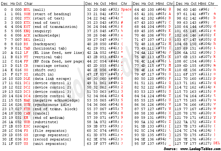
This thread has the purpose to regulate the LEDs in the lamp. Depending on the series selected by the user, the thread sets the corresponding LEDs needed to the right color. The general procedure for each series was to check the first two to three digits of the resistance and select the corresponding color following the color coding table. In order to do this, we converted the resistance into a string of ASCII characters. We then called a helper function that checked each individual digit and assigned the corresponding color to an array in the order the digits appeared. To check which character corresponded to which value, we took the table on the right as reference. Then the corresponding LED was set to the correct color selected and the around ones were set to a background color to ease the recognition of the color band. One crucial part we implemented was the tolerance calculations. To calculate tolerance, one would take the nominal value of the resistor, subtract the actual value and divide by the nominal again to get the percentage fluctuation of the resistance. As we will see later in the report, this constituted a limitation on our design as we don't have access to the nominal value, leading to a tolerance band not very accurate to the one stamped on the resistor.
Another implementation in this thread was the setting of the decoration LEDs around the project. These decorations were more complicated to set up than one would expect, as we had to modify the LED header and C-file to accommodate multiple strips of LEDs. What we did was to implement the
send_led_data() function to accept an int, indicating through which pin to send the assigned color. Since our decoration strip and our lamp strip were connected to different pins, making this slight but powerful change allowed us to have multiple strips run concurrently and almost independently.
Audio thread
The audio thread has the particularity to run on core 1 so to not be interrupted by other threads and can only be run when the audio button has been pressed, otherwise it doesn't run. When running, the thread has the role to fire the DMA channel initialized in main() with the right audio file, depending on the resistance recorded at the moment the button was pressed. Firstly it fires the DMA channel saying "
The resistance is: " and waits 1.5 seconds. The wait is crucial as without it, the sound would be cut off by other sounds fired at the same time it should be playing. After the first sound has finished, we coded a for loop checking each digit of the resistance and firing the corresponding sound saying that digit. In order to do it, we once again convert the resistance value into a string of ASCII characters to be able to loop through them. For each digit, we check if the character corresponds to any number so as to fire the corresponding sound. To check which character corresponded to which value, we took the table mentioned above as reference. Crucial again is the line
sleep_ms(700) , as without it the sounds will cut each other over without having the time to effectively play in their fullest. The last sound fired is the sentence "
Ohms ", closing the for loop. Finally, the
audio variable is set low again so as to reset the whole system until the audio button is selected again.
Fundamental for the implementation of this thread is the understanding of DMA (Direct Memory Access) channels. DMA channels are a very powerful tool because it allows to initiate commands or send data without the use of CPU and memory. Instead, it uses the flash memeory of the RP2040 to indipendently fire what is stored in it when it is called to. In this case, the DMA channel is configured in
main() to take a C-array representing the amplitude of a sound to reproducewith also specified how many element the array has as it needs to know when to stop. By doing so, the RP2040 doesn't need to do any computation and when the code indicates the DMA channel to fire its content, it does so without overloading the CPU with data.
Python file: WAV to C-Array Conversion
In order to use the DMA channels, we needed our sound to be C-Arrays saved in flash memory (saved in an header file which the main file has access to). To make this happen, after recording our 12 different sounds, we converted them into WAV files of 16 bits with a frequency of 44.1 kHz. This conversion is extremely important as our code would only work with a 16 bit running at 44.1 kHz files. After making sure this conversion happened, we created a python file, taking as starting point suggestions on the internet, that reads the WAV file and converts it into an array of ints. Once done that, we just needed to convert the range of values to the one the RP2040 recognises (0, 4095) and finally append in front of each element in this array the configuration bits. These configuration bits are 4 bits length data used to indicate the DMA channel to what we want the data (the remaining 12 bits) to be fired to, in this case the DAC. Once all transformations are completed, each element is saved in a C-array divided by a comma, ready to be copied in the header file before mentioned to be at the DMA channel disposal.