PID control of a 1D quadcopter
by Guadalupe Bernal (gb438), Ding Yang (dy297), Ziyang Ren (zr86)
ECE 5730 Final Project Report submitted on Dec 15, 2023
Project Introduction
For our final project, we created a simplified Pico Quadcopter that can be controlled through a serial interface and allows a user to direct the quadcopter to fly up and down a metal tube.
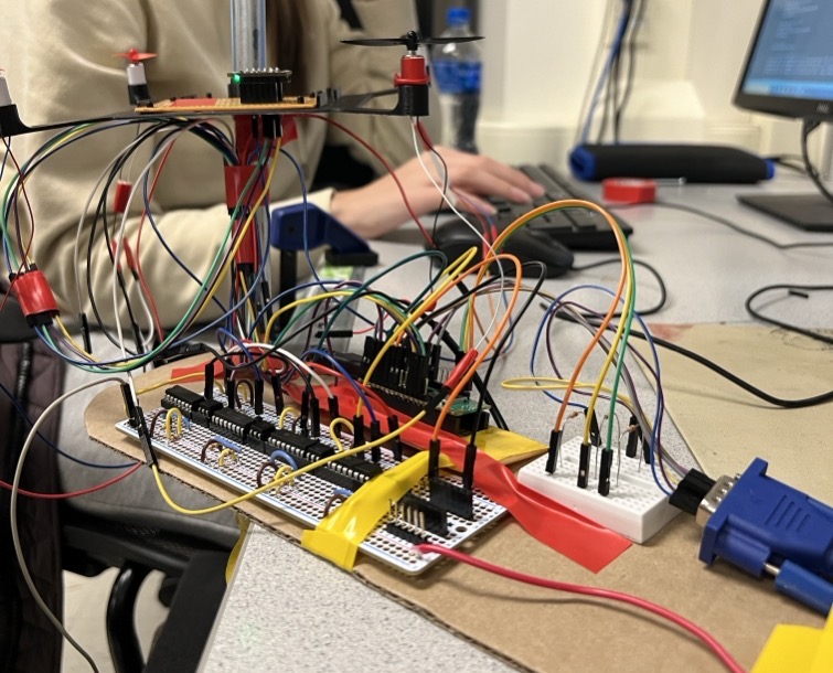
To complete this project, we designed, tested, and developed a circuit that could control 4 DC motors. This was powered by a 1500mAh, 100C battery. The electronics were placed on the table while the quadcopter lifted itself and an IMU up and down while held in place by a metal tube. The Raspberry Pi Pico controlled the motors through the motor control circuit. It was also connected to the computer through serial communication. We did this so that the user could control the quadcopter through serial commands. We successfully created a quadcopter that could lift itself and be controlled directly.
High Level Design
Background
The design of a quadcopter involves complex calculations including maximum current, battery capacity, and the current bearing ability for each component in the circuit. In general, it is a combination of algorithm design and hardware implementation. Although it is a cool idea to build a quadcopter with all 6 DOF that can really fly and go wherever as instructed, it is too much work for a 4 weeks project, so we punched a hole at the center of its body and run a metal bar through it, which limits its degree of freedom. With this kind of limitation, the accuracy requirement for the PID controller is lowered . What’s more, it is more convenient for us to test the drone without worrying about damaging it.
Background Math
1. Complementary Filter
In order to make the quadcopter fly we needed to do a variety of calculations. We began by analyzing how we can calculate the estimated angle using acceleration data. The equations below show the computation of the roll angle and include the complementary filter coefficients we used. This approach was identical to the approach we used in lab 3. Though there was the addition of including both the acceleration in y and in x. This is because the roll angle requires both. We computed the pitch in the same way.
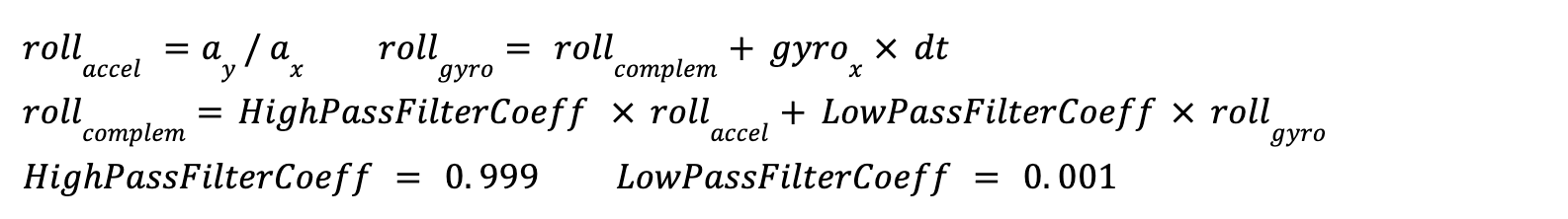
Since we do not have acceleration data for the yaw angle, we will not be able to apply complementary filters on yaw angle. Thus, in order to compute it, we only used the angular speed for yaw. The equation below shows this computation.

2. PID Controller
Then, with complementary angle and goal angle, we use a pid controller to determine the correction value for roll, pitch and yaw. As we learned in lab 3, the PID controller requires three parameters to be tuned: proportional, derivative and integrator.
- Kp is directly proportional to the current error, it helps reduce the steady-state error of the system.
- Ki is proportional to the accumulated value of the past errors over time. It helps eliminate steady-state error that Kp cannot handle alone.
- Kd is proportional to the changing rate of the error. It helps in damping the system's response and relieve oscillation.
The equation below shows how we considered all three PID controller parameters in order to compute the correction variable.

3. Throttle Allocation
The pose that the IMU is installed in is not aligned with the direction that motors are installed. So the correction output that we generated from the pid controller cannot be directly applied to the motors. The way that IMU and motors are installed on the frame are shown below.
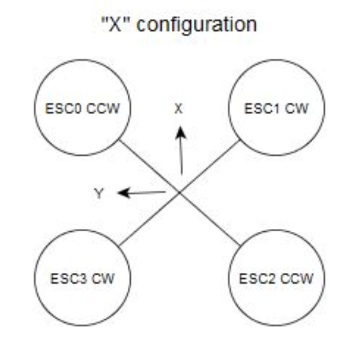
There are throttle allocation equations for this:
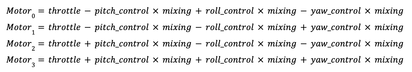
Because the x direction of IMU and the positive direction of the drone forms an angle of 45 degrees, so the parameter mixing is set to 0.5 .
Logical Structure
The logical structure of our project was split into two major parts. The first part was the hardware and the second part was the software. The software had three main components: motor control, VGA plotting, and serial communications. The hardware structure also had three main components: the physical quadcopter, the structure holding up the quadcopter, and the electronics. All of these components will be described in detail throughout the following report.
Software/Hardware Tradeoffs
In terms of hardware trade offs, we had a lot to consider. For example the weight / power trade off of the quadcopter. The more weight we had the more power we needed to be able to lift and the stronger the motors we needed to be able to fly. Unfortunately, this trade off was too much and we ended up needing to remove the hardware and battery off of the quadcopter in order to be able to fly it. The software was much more manageable and did not require as many trade off considerations. We did consider efficiency and ran multiple threads in parallel in order to control the motors, plot to the VGA, and run the serial interface concurrently.
Relevant Copyright Information
In terms of intellectual property considerations—the hardware design idea comes from Robu [1]. But we redesigned the physical quadcopter and all the electronics. For the software, we used an open source project [1] on Github.
The Federal Communications Commission (FCC) has guidelines on the frequencies that RF transmitters are permitted to operate at. Quadcopters would be classified as “intentional radiators” and need to meet the Specific Absorption Rates (SAR) set by the FCC. Since we bought our transmitter on Amazon, it already meets all the regulations to be sold in the United States. Since testing is done under maximum power conditions, there is no way we would be able to exceed or go out of range of the FFC’s regulations.
Program and Hardware Design
Program Details
The main structure of the program is similar to Lab3: 1D helicopter, but in order to improve the function from helicopter to quadcopter, we combined some control logic from an open source project liourej/CodeDroneDIY on Github into the original code. We used it as a base for the mathematical equations but needed to heavily modify and adapt it to our own design, especially considering the different hardware setup. The graph describing the hierarchical structure of the program is shown below:
1. Hardware Interface
- IMU: We use the interface provided in mpu6050.c to get gyro and accelerometer raw data.
- PWM output: We use two PWM slices, index 0 and 1, each has two channels, so we have four pins for PWM output, which are GPIO 2, 3, 4, 5. We then use the pwm_set_chan_level() function to set the PWM output for each channel, which ensures that the output value of each channel can be different according to the controller calculation.
- IRQ: Frequencies are the same on two slices 0 and 1, so we only need one slice to run the interrupt routine. In our program, slice1 calls the on_pwm_warp() function, it runs at frequency 1000 Hz, the interrupt function deals with all the logics related to angle calculation and pid control calculation.
2. Angle Calculation
- Roll & Pitch: Two axis of acceleration data are used to calculate a rough estimate of angle, it’s not drifting but has low accuracy. Gyro speed data has high accuracy but will drift over time. So using complementary filters to get better estimation for these two angles.
- Yaw: No acceleration data can be used, only using gyro speed data.
3. PID Algorithm
- Roll & Pitch: Position based PID control loop.
- Yaw: Speed based PID control loop.
Roll and pitch controllers share the same PID parameters, and they can be the main. We get pitch, roll, yaw control output, but imu and the head of the drone are not aligned, they have an angle of 45 degree.
In order to calc four motors’ PWM, we need to get PWM output in a mixing way. It is the base throttle add up with some combination of pitch, roll, yaw control output. To calculate the height, we used the filtered accelerometer data from the z axis to calculate the current height, it is not complementary so not accurate, but can give an estimate of height.
4. Software Interface
For the software interface we decided to use two approaches in combination. First we connected the Raspberry Pi Pico to the computer through a serial communication interface. This gave us the ability to control various parameters throughout our code during debugging. The first parameters we added to the interface to allow us to have control were the PID Kp,Kd and Ki values. Then, we connected the Raspberry Pi Pico to the VGA so that we could plot the various angles we were computing onto the monitor. We also plotted to the VGA the PID controller parameters, values of the current angles, and more debugging information throughout. Then finally, we added a few more options to the software interface to allow us to turn the quadcopter on and off, and control the power. These interfaces were crucial to our testing and debugging process. We added a virtual button option on the serial interface that allowed us to run a mini program, similar to that in lab 3, that would take the quadcopter through a series of predefined motions. This process included the quadcopter moving up 10cm, hovering for 3 seconds, and then flying up another 10cm, hovering for another 3 seconds and then finally slowly decreasing back to the ground. This can be seen in our youtube video demo below!
Hardware Details
In the large hardware design side of the project, our objectives were to build a small drone controlled by the Pico RP2040, to design a circuit capable of handling high-current demands from the motors, and to ensure stable and efficient power supply.
The table in Appendix B shows a summary of the components, model, purchase links, and cost of all the components we needed which will be mentioned throughout the following section.
Circuit Design and Development
The original circuit components comprised a MOSFET, capacitor, and diode. However, as the project progressed, we encountered several challenges that necessitated significant revisions to our design. We replaced the initial components with a Darlington transistor array to manage voltage requirements better. This change was primarily due to the high current demands of our chosen motors, which draw 1.8A at full duty cycle and 1.2A at 50% duty cycle. Our initial oversight of these current requirements led to the failure of our first circuit version. We redesigned the circuit to handle the higher current, employing four Darlington transistors since each channel can handle only 500mA. Additionally, we upgraded our power supply to a 1500 mAh, 100C battery capable of supporting up to 150A current. This new battery was estimated to last around 15 minutes under an average current of 6A.
Physical Quadcopter Build
To build the quadcopter we first modeled it on Onshape (Appendix B). The figure below shows this model. We made the design as lightweight as possible while still being structurally sound. Then we printed it out, attached the selected motors, and the circuit designed above. The quadcopter had a hole in the middle in order to limit its range of motion using a metal tube as described in the section below.
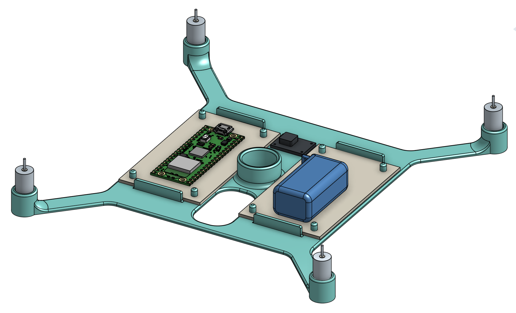
Even though we were very happy with how the model came out, once we debugged the circuit, we came to the conclusion that we would have to remove the electronics off of the physical quadcopter itself and place them on the table while connecting only the wires to the quadcopter itself. We did decide to leave the IMU on-board since that is a necessary component in adjusting the quadcopter height and leveling. The picture in the section below shows this final design.
Physical Quadcopter Holding Build
In order to ensure safety and simplify the project to fit in the 4 week time frame, we decided to limit the degrees of freedom the quadcopter was able to navigate, as we described in the background math section. The picture below shows the full and complete final setup.
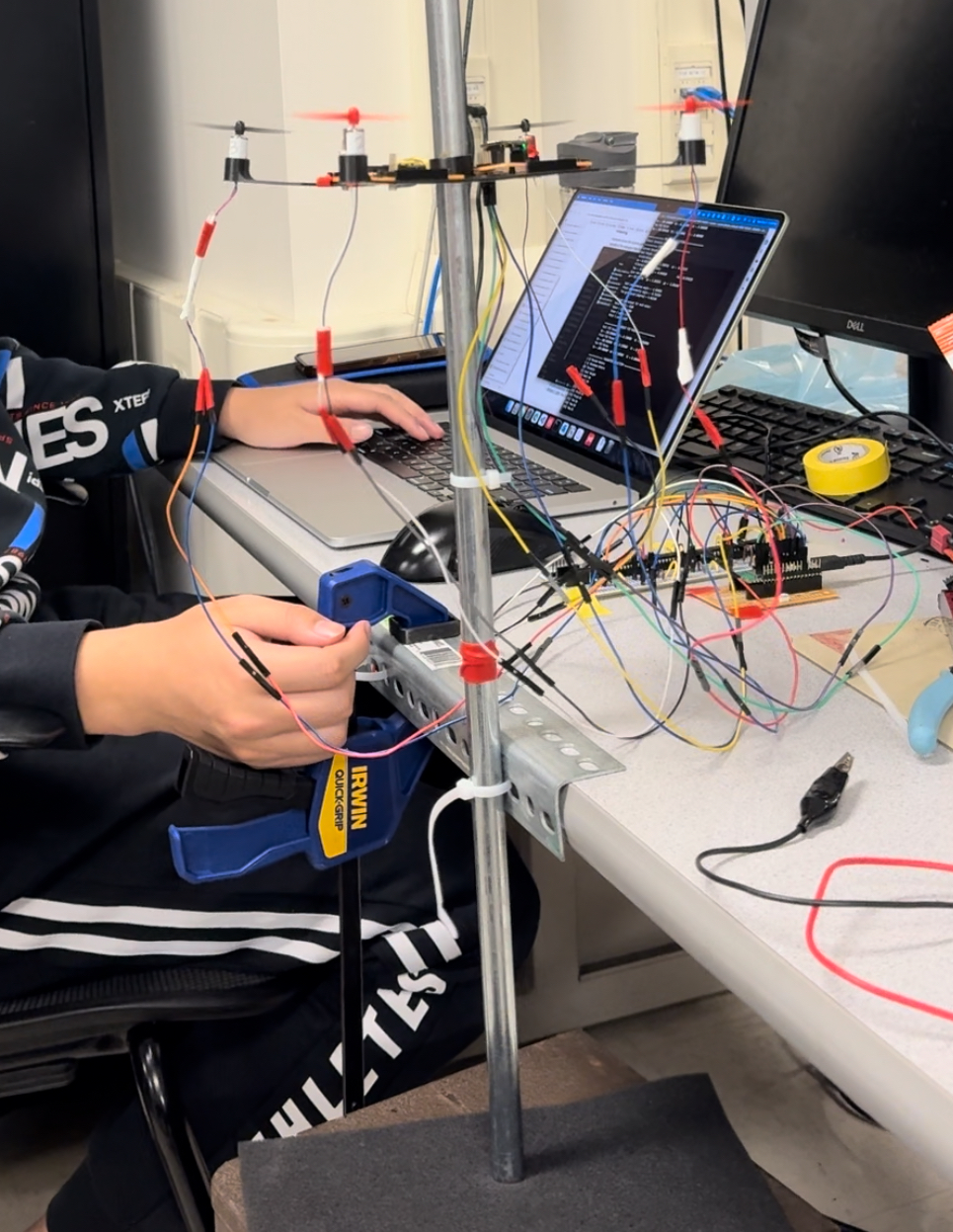
We used a metal rod to constrain the range of motion of the quadcopter. Then, we attached the rod to the table using a metal bracket, zip ties, and a clamp. Since the rod would slip down through the zip ties we had to place a box underneath the metal rod. With all of these components in place the rod was very stable and supported the quadcopter appropriately and as expected.
Challenges and Solutions
We had a large number of issues to solve. Below they are listed:
1. Soldering Issues
Because of the complexity of our circuit we mistakenly missed soldering a single pin, which led to extensive troubleshooting. Our solution was to implement a systematic approach to soldering and thorough inspection post-soldering. This involved first planning out the paths in detail, and having two people soldering together, one to solder and the second person to verify and direct. Another problem we encountered because of soldering issues was a lack of isolation between MCU and power ground which led to damage. Our solution was to ensure proper isolation in the revised design. The next problem we encountered was that the VSYS pin was damaged by powering from utilizing both the USB and battery to power the Pico. Unfortunately, there was no solution and we had to replace the Pico but we were sure to only power the Pico from USB while testing.
2. Motor Current Under Load
The second problem we encountered was that we underestimated the current draw of motors with propellers. Our solution was to conduct tests under load and research motor specifications in-depth. Once we did this, we found a few big batteries to use. Because of the current load, the next problem we encountered was that our initial battery choice was inadequate, lasting less than 4 minutes. Our solution was to select a higher capacity battery, balancing weight and power needs.
3. Motor Thrust
The third large problem we encountered was that the motors couldn't generate enough thrust for the entire circuit. Our solution was to limit the hardware being lifted to the IMU, keeping control circuits on the table.
Results of the design
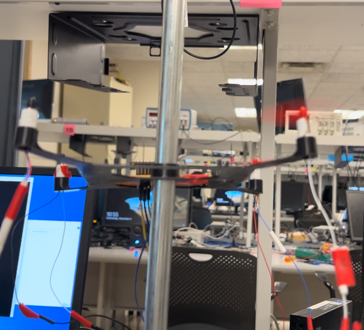
The quadcopter worked relatively well! The figure below shows the final quadcopter design!
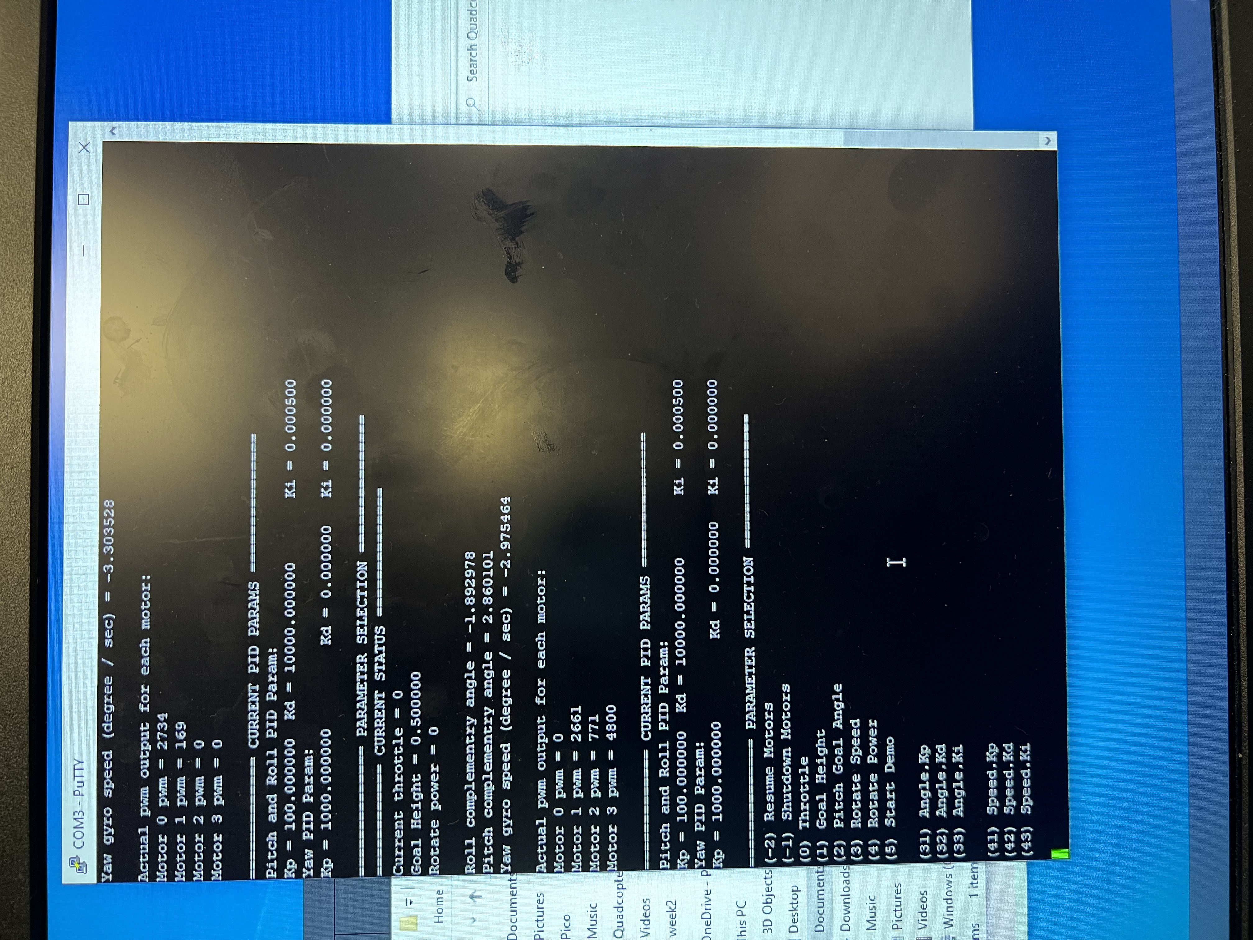
The figure below shows the finalized serial interface and all of the options available for debugging, setting the PID controller values, and for the user to use the quadcopter.
We also set up a connection to the VGA in order to display the current status of the quadcopter, the figure below shows this finalized connection while the quadcopter was flying.
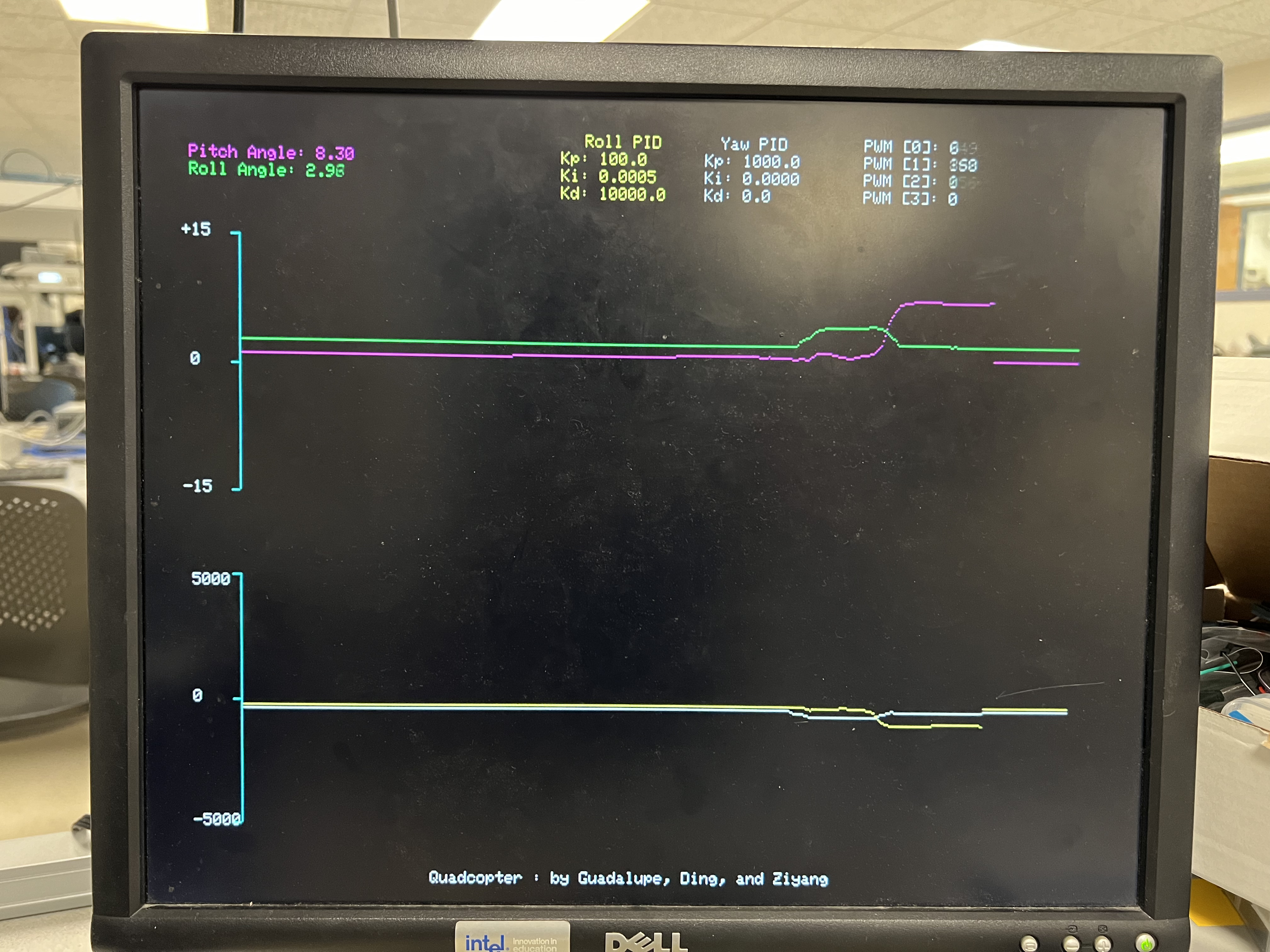
The code ran at 1 kHz speed. We enforced safety in our design through various ways. Since a quadcopter is a relatively dangerous flying electronic object, there are many usability, and safety standards we must account for. For safety, we had all the electronics on the table aside from the IMU, and limited the quadcopters motion to a vertical stick. This will prevent it from potentially flying out of control and throughout the lab. Since we used a LiPo battery, we made sure we had access to a proper LiPo charging/discharging system.
To conclude the results section, through a process of trial, error, and revision, our project has successfully addressed a range of challenges, leading to the development of a functional small drone prototype.
Conclusion
This project was a roller-coaster ride in terms of the challenges we face and how quickly we adapted. Every time we worked on the project a new issue would arise that we would need to figure out. We are overall happy with the final result, even if we didn’t meet all of our original goals. Next time, we would be sure to be more careful scoping out the hardware requirements of the project before ordering hardware and extensively check circuits while soldering instead of just afterwards.
As we described in the Results section, we considered all relevant safety standards before beginning designing. We believe we were successful in creating a quadcopter that functioned safely and intensively in the laboratory setting. The limitations in the range of motion and having all the electronics on the table instead of on-board allowed us to ensure the quadcopter would not fly away. The motor propellers were also not strong enough to injure. As we described in the HLD, we considered all relevant copyright and intellectual property before beginning our design. We made sure to use open-source code for inspiration and mathematical guidance but overall developed our models. There are no patent opportunities for this project, as it was an exploration and a learning experience.
Check out the video below to see our project!
Appendix A: Permissions
The group approves this report for inclusion on the course website.
The group approves the video for inclusion on the course youtube channel.
Appendix B: Code Sources
Fully commented code can be found: https://github.coecis.cornell.edu/gb438/ECE5730Labs.git
Quadcopter model body can be found: https://cad.onshape.com/documents/6ccaaeb67fd8d961ac6aa1b7/w/a5322159e23428a1782a0fd0/e/e3a827eb7f9e5522bcd7de76?renderMode=0&uiState=657c7d507e6f5d764b7187b1
Appendix C: References
[1] Code we referenced for our project, Robu link, gave us ideas for the code: https://robu.in/
[2] Code we referenced for our project, showed us math calculations: https://github.com/liourej/CodeDroneDIY
[3] Cost Table
| Component | Model | Purchase Link | Cost ($) |
|---|---|---|---|
| Frame | - | 3D printed | 0 |
| DC Motors | 8520 micro coreless motor | https://www.amazon.com/YoungRC-Coreless-Brushed-Propeller-Quadcopter/dp/B078NL9KQQ/ | 10.99 |
| Propellers | 55mm CW2 + CCW2 | Contained in the above link | 0 |
| Battery | Lipo 1300mAh, 100C | https://www.amazon.com/dp/B08L3G2BFV | 29.99 |
| Accelerometer | MPU6050 | Already have one | 0 |
Total Cost: $41.98