ECE 4760 Final Project: Theremin with 3D Image
Dive into a unique audiovisual experience as you interact with our project: a theremin that controls the movement of a floating cube.
Becky Lee (bl478), Annabel Lian (ayl48), Erica Li (el549)
Dive into a unique audiovisual experience as you interact with our project: a theremin that controls the movement of a floating cube.
Becky Lee (bl478), Annabel Lian (ayl48), Erica Li (el549)
The theremin works using an ultrasonic distance sensor that measures the distance of the user’s hand with sound pulse detection, subsequently altering the sound based on the measured distance. Then, based on the distance, we would change the amplitude and frequency of the sound wave we were synthesizing to produce a new sound. Using Pepper’s ghost effect, we projected an image of a cube that rotates about both the x and y axes onto a 45-degree angled plastic pane called a Pepper’s Ghost reflector. The cube rotates clockwise or counterclockwise depending on the direction of our hand’s motion in front of the distance sensor. Concurrently, users hear varying sounds and observe changes in the cube’s rotation in response to the distance measured by the ultrasonic sensor.
Becky and Erica are interested in audio synthesis and music, and Annabel became interested in Pepper’s Ghost effect after watching a Magic School Bus episode. After brainstorming project ideas, we thought it would be interesting to combine our ideas into an interactive audio visual project.
A theremin creates an electromagnetic field around the two metal antennas attached on the two sides of the theremin. Players could change both the pitch and volume of the note produced by the theremin by moving his or her hands in different directions around two metal antennas.
For our implementation of the theremin, we decided to use additive direct digital synthesis (DDS) so that we could produce sounds that had one fundamental frequency and harmonic overtones. Direct digital synthesis is where a digital signal is generated based on mathematical computations and manipulations of formulas such as cosine and sine waves based on time. Depending on the time, the frequency of the signal would change and thus a new sound would be produced. Also, the attack, sustain, and decay times that determined how fast the sound would ramp up, sustain that sound, and then let the sound die out respectively could be changed in order to change the overall sound of the note. Then, this digital signal is converted into an analog signal that can be relayed to a DAC (digital to audio converter) and then to an external speaker. Additive DDS is just the addition of multiple waves in order to create a new signal.
We started to make the notes based on the following fundamental frequencies:
In order to create the harmonics, we used the following procedure:
In the table below is the following conversions we made for the four fundamental frequencies mentioned above and their four respective harmonics:
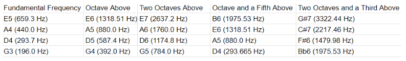
From the fundamental frequencies and harmonics as described above, we were able to make distinct notes albeit a bit distorted which will be described below in the programming/hardware section.
For each note, we used a simple sine wave of the form sin(pi*frequency*time) and added together each frequency (fundamental frequency and harmonic frequencies). Then, instead of the frequency changing based on time, we chose to make the frequency change with distance in order to mimic the behavior of a theremin.
Depending on the distance, the fundamental frequency would change which would result in a different pitch.
We had two ways of using the distance to change the sound being produced.
Since we did not want to limit the user to only being able to hear a certain set of notes, we decided to create two modes based on an external button press.
When the button was not pressed, we would be in the mode of discrete notes. When the button was pressed, we would be in continuous notes mode.
The software trade off faced by the sound production was that the time that it took for the distance to be calculated from the ultrasonic sensor created delays which slowed down the speed needed in order to enter the interrupt service routine to produce the sound. Therefore, even if we were sampling at around 40 kHz or so, the delay due to measurements from the ultrasonic sensor ultimately created some distortion when producing the sound and thus led to some unexpected behavior which we describe more in detail in the analysis section.
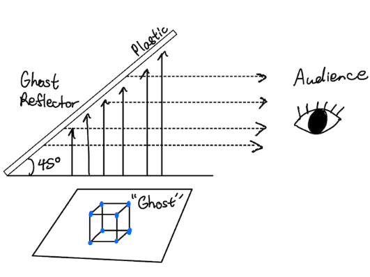
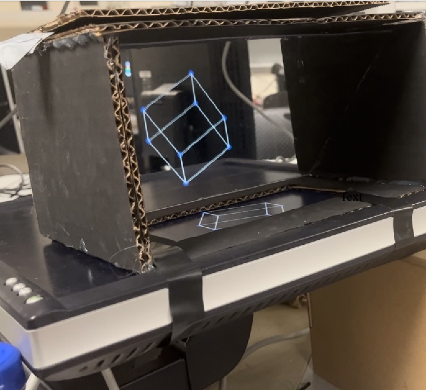
The central element of our visual element is our Pepper’s Ghost effect box. We followed the tutorial from this link to make our own. However, we adjusted the dimensions to accommodate a larger image. Pepper’s Ghost effect is a visually appealing illusion technique that can be traced to the mid 16th century. A clear pane faces the “ghost” at a 45 degree angle. The “ghost” can be a real or recorded image. When the audience looks at the pane, they see a reflected image that appears to have depth. In our project, the VGA screen will create the ghost image.
To draw the cube, we had to rely on matrix operations. We started out by determining the coordinates of a unit cube (offset from the origin by 1).
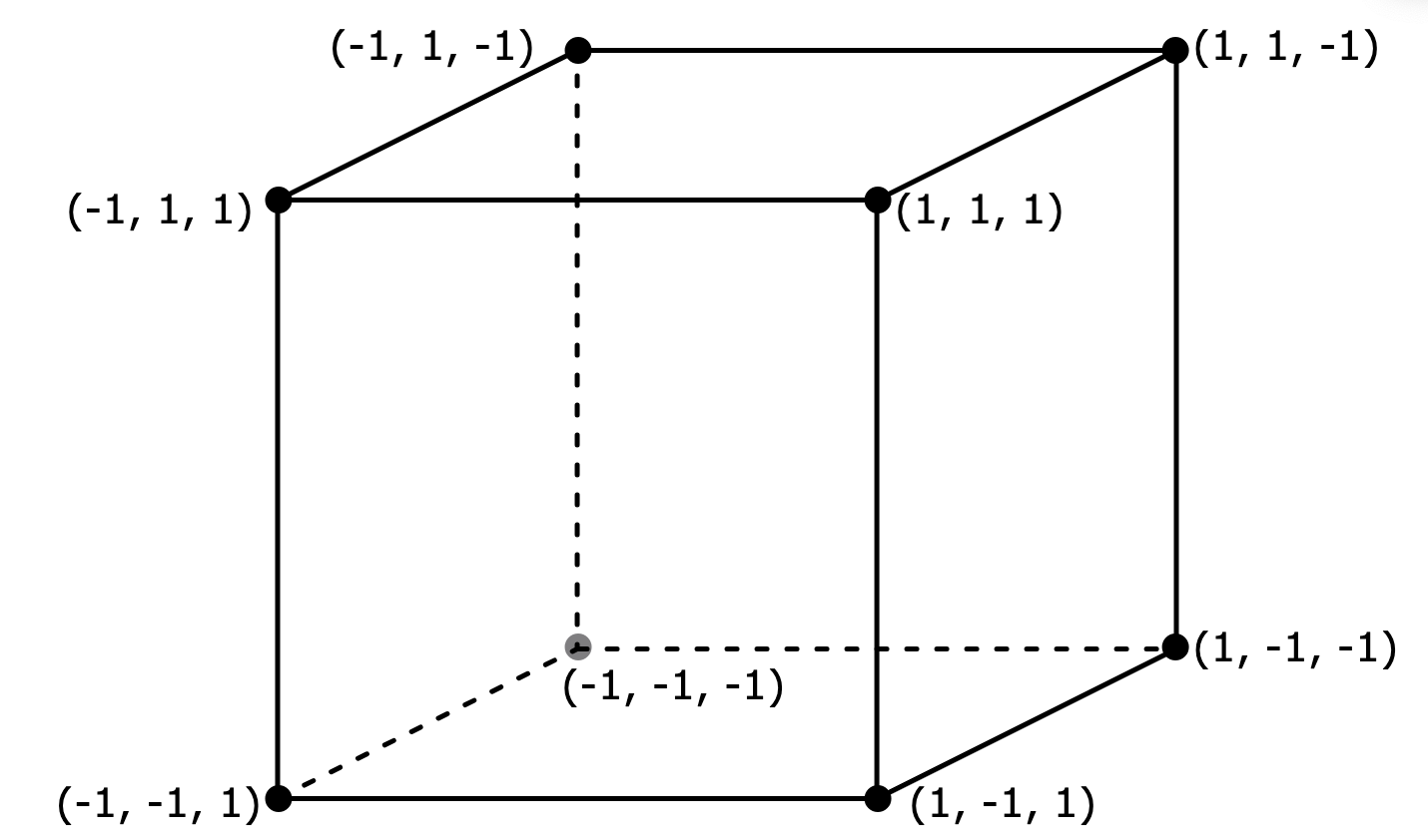
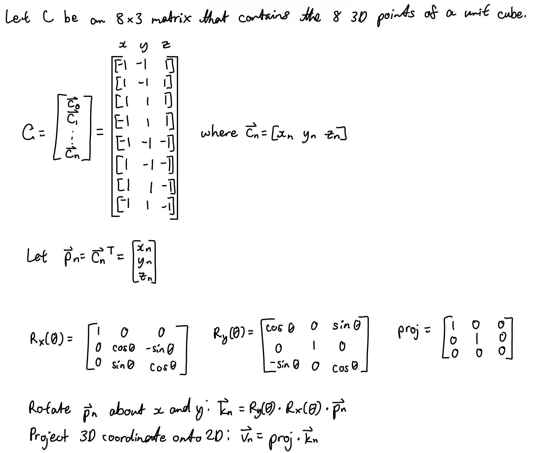
Then we put these coordinates into an 8 by 3 matrix C as shown below. In our code the matrix is made up of 8 row vectors. The first column contains the x coordinates, second contains the y coordinates, and third contains the z coordinates. We used a function to transpose the row vectors into column vectors so that we could perform matrix multiplication for the rotations. The standard 3 by 3 rotation matrices are shown along with the projection matrix. To rotate each point about the x and y axes, we had to multiply their column vectors with both the x and y rotation matrices. To obtain a 2D projection of each point for our VGA drawing, we multiplied the resulting column vectors by the projection matrix.
Both the theremin and graphics had the hardware tradeoff between using an ultrasonic distance sensor and a radar sensor. While the radar sensor may have been able to detect the distance more accurately, we ultimately decided to use the ultrasonic distance sensor since there was already direct compatibility between the analog measurements being made and the conversion to digital outputs which were to be used by the RP 2040.
In regards to the software tradeoffs, both the theremin and graphics relied on the distance measurements from the ultrasonic sensor which came from a thread called protothread_core_0. Therefore, in order to ensure that the graphics and the audio did not interfere with each other, we decided to put them both in the interrupt service routine rather than in two separate threads which could cause timing issues and delay either the graphics, sound production, or both.
If one of the threads was taking too long, that thread could block all of the other threads from running and then that would interfere with both the graphics and sound production as well as the distance measurements.
As far as we know, there is no direct patent, copyright, or trademark in regards to the overall result of our project. The theremin itself was patented in 1928 ([1]). However, since we did not directly use the theremin in our project but instead created our own rendition of what we thought a theremin should behave like, we believe that we did not violate the patent of the theremin.
The idea for the structure used to create Pepper’s Ghost effect was drawn from this YouTube Video. However, we changed the dimensions and swapped out materials to suit our own project ([2]).
The fundamental coding logic for the cube graphic was taken from this Python YouTube video and converted it into C code for integration into our project ([3]).
We used an ultrasonic sensor (HC-SR04) that measured distance based on ultrasonic waves. In order to power up the ultrasonic sensor, we needed to supply 5V. WE accomplished this by using an external power supply provided to us in the lab.
The ultrasonic sensor’s trigger pin was connected to the RP2040’s GPIO 15 and the ultrasonic sensor’s echo pin was connected to the RP2040’s GPIO 14.
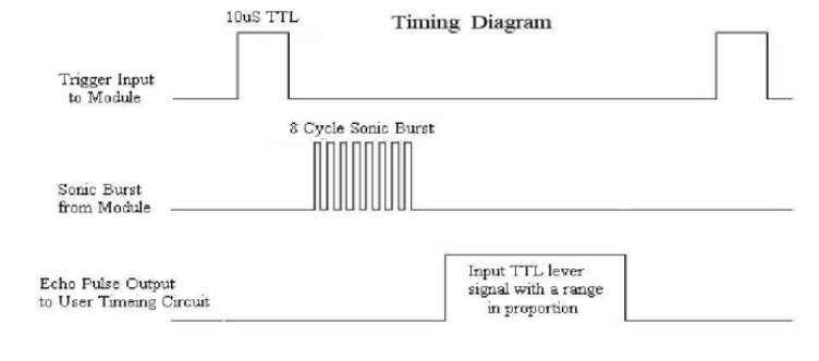
As per the datasheet and in the figure shown below, in order for the ultrasonic sensor to detect the distance an object is from the ultrasonic sensor, a 10 microsecond square wave pulse must be sent from the trigger pin. The trigger signal would result in an 8 cycle sonic burst at 40 kHz from the ultrasonic sensor in order to trigger the echo pin. Then, the time between the sending of the trigger signal and receiving of the signal by the echo pin would be calculated. The difference in the time would be used to calculate the distance.
For the hardware, we used a digital to audio converter (DAC) and external speakers in order to listen to the sound being produced via the additive DDS algorithm. The DAC would sample the signal at 40 kHz and take the digital signal produced by the code and turn it into an analog signal which would be sent out to the speakers.
Also, we used an external button to change modes between discrete and continuous sounds. The external button was connected to a 300 ohm resistor. The 300 Ohm resistor was then connected to GPIO 11 on the RP2040.
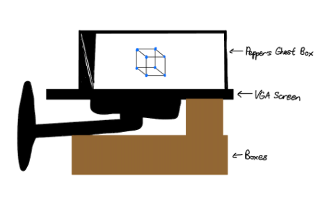
The physical setup for the visual aspect of our project is depicted below. We laid the VGA screen on its side on top of boxes so its screen was horizontal. We then placed the Pepper’s Ghost box on top of the VGA screen so that the square opening was on the screen.
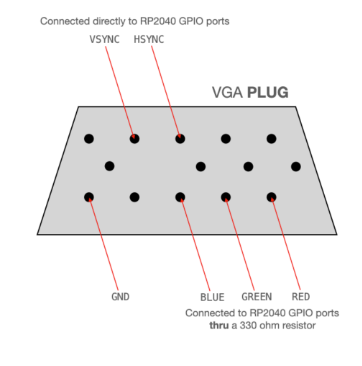
The VGA plug connections are shown below. For the red, green, and blue connections, it is important to remember to connect them to the RP2040 through 330 ohm resistors.
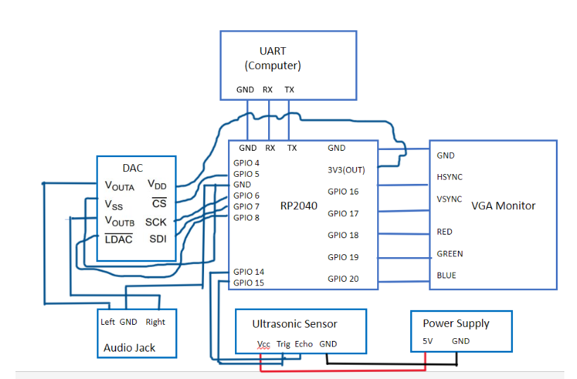
Overall Hardware Schematic:
The audio synthesis code takes input from the distance measurements and from button presses to determine the specific state that must be used when entering the ISR. If the button is not pressed, the range that the distance measurement falls under determines the specific state that must be entered in the ISR (with each state corresponding to a different note being produced). We called this mode discrete notes. If the button was pressed, then we immediately go to the state in the ISR that produces continuous sounds. The continuous sounds are produced by taking in the scaled version of the distance measurement as an input for modifying both the frequency and amplitude of the sine wave.
The graphics code for the rotating cube relies on the VGA driver given to us by Hunter Adams. All the drawing functions are implemented in the vga_graphics.c file and we include its header file in our project code. Before we discuss the functions that are used to generate the cube animation, it is important to discuss the global variables that will be used in the matrix operations involved. Given that C does not have built-in matrix operation functions, we had to develop our own implementations. We have multiple matrix multiplication functions for each calculation because reusing the same multiplication function for different array parameters proved to be more inconvenient for us in C. Each matrix multiplication function will utilize its own intermediate array variable to store its result.
| Global Variable | Description |
|---|---|
| float scale = 50; | Multiplier used to change the size of the rotating cube. |
| float angle = 0; | Keeps track of the cube angle. Variable will be increased or decreased depending on the distance. |
| float points[8][3] | Stores 3D coordinates of the cube’s 8 vertices. The cube coordinates stored here are the coordinates of a unit cube that we can scale with a multiplier. |
| float proj[3][3] | Projection matrix that maps 3D coordinates onto 2D. Used to multiply |
| float proj_points | Stores 2D projected points that will be drawn on the VGA |
| volatile float dist | Stores the currently detected distance from the distance sensor. |
| volatile float prev_dist | This variable keeps track of the previous distance of an object or hand from the distance sensor. This variable will be used for comparison with the current distance to determine which direction the cube will rotate. |
| float rotated_x[3][1];
float rotated_y[3][1]; float projected2d[3][1]; float reshaped_vector[3][1]; |
3 by 1 arrays that will be used to store intermediate results from our matrix operations. |
| Code | Description |
|---|---|
| float getPulse(int trigPin, int echoPin) | For the getPulse() function, we created two variables called begin_time and end_time. We kept track of the time by using an internal clock in the RP2040 called time_us_32(). The begin_time would keep track of when the trigger pin first received the signal from the trigger pin which is determined by the echo pin going high. The end_time would keep track of when the echo pin finished receiving the signal from the trigger pin which is determined by the echo pin going low. The difference between the end_time and the begin_time is the time that it took for the pulse from the trigger pin to reach the echo pin. Depending on where we placed our hand in relation to the ultrasonic sensor, it would take either a shorter or longer period of time for the pulse to be received by the echo pin. When we put our hands further away from the ultrasonic sensor, it resulted in a longer time for the pulse to reach the echo pin. When we placed our hands closer to the ultrasonic sensor, it took less time for the pulse to reach the echo pin |
| float getCm(int trigPin, int echoPin) | In the getCm() function, we just multiplied the pulse length by a constant 0.0172 as described in the datasheet for the ultrasonic sensor in order to convert the pulse length to a distance measurement in centimeters. |
| static PT_THREAD (protothread_trigpulse(struct pt *pt)) | trig_pulse created a 10 microsecond square wave pulse. The trigger pin was first set to low for 1 millisecond and then set to high for 10 microseconds and then back to low for 10 milliseconds. |
| void connect_points (int i, int j) | Draws a line between two vertices with indices i and j. This function uses the draw line function from the vga_graphics file. |
| void reshape(float vector[3]) | Reshapes a 1 by 3 vector to a 3 by 1 column vector for our matrix multiplication operations. The result is stored in reshaped_vector. |
| void mult_x(float matrix[3][3] , float b[3][1]) | Matrix multiplication function used to multiply the x-rotation matrix with the reshaped_vector. This rotates the cube vertex about the x-axis. The resulting vertex is stored in rotated_x. |
| void mult_y(float matrix[3][3] , float b[3][1]) | Matrix multiplication function used to multiply the y-rotation matrix with the rotated_x. This adds rotation about the y-axis. The resulting vertex is stored in rotated_y. |
| void mult_project(float matrix[3][3] , float b[3][1]) | Matrix multiplication function used to multiply the projection matrix with rotated_y. This maps our 3D points onto 2D points that we can draw on the VGA. The result is stored in projected2d. |
| void drawCube() | Draws one instance of a cube on the VGA screen. Starts by clearing the screen of the last instance first. Calculates rotation matrix based on the current angle. In a for loop, the following is completed for all 8 cube vertices:
After all the points are drawn, lines are drawn between specific points to create the cube visual. |
| static PT_THREAD (protothread_core_0(struct pt *pt)) | We created one thread in core 0 called protothread_core_0 that would take distance measurements. Depending on the distance measurements, we would transition to different states in the interrupt service routine (ISR) where the states would correspond to different notes being played.
Protothread_core_0 would first get the distance measurement from the function getCm() and store it in a global variable called dist which would get referenced later in the thread. Then, we go into different conditional statements based on whether the button was pressed or not (pressed meaning the button had a value of 0 and not pressed meaning the button had a value of 1).If the button was not pressed, then we would go to state 5 which would produce a continuous sound (described later when we explain the ISR part of the code). If the button was pressed, then we would look at the distance measured by the ultrasonic sensor and determine which state we could go to in the ISR.
Then, after we ran through the conditionals in our thread to see which if any were met, we would set a flag high (in this case GPIO 2 would be set to high) and we would enter the ISR. |
| static PT_THREAD (protothread_core_0(struct pt *pt)) | In the ISR, there are 5 states. Each state used the variable amplitude which defines the volume of the sound we were trying to produce. The default value of amplitude was 1. Each state also had its own attack, sustain, and decay time as defined below so that we could produce different sounds.
The following are the initializations for the attack, sustain, and decay times:
After the ISR finished the audio synthesis, the flag would be set back to low (in this case GPIO 2 would be set to low) which allows another thread to run. |
Below is a description of each of the states in the ISR.
| State | Description |
| State0 | We created an A-note by adding together pure sine waves using the fundamental frequency and harmonics as described in the theremin part of the concept section.
Each sine wave took in a variable called count_0 in order to increment the phase of the sine wave. After we added the sine waves together to create the A_note, we would increment the phase_accum_main_0 which would be used to figure out the correct sine wave to output to the DAC. The sine wave sent to the DAC would come from a sin look-up table that took in phase_accum_main_0 as the input. Then, the sound that was generated from the DAC was determined by the attack time which we called SWOOP_DURATION for this state in order to ramp up the amplitude. Also, the attack time - decay time which we called SWOOP_DURATION - DECAY_TIME in this state determined how fast the amplitude decayed. The sine wave would go to output channel B of the DAC which would connect to the external speakers via serial peripheral interface (SPI). Then, we would increment the count_0 and start the process over again until count_0 is equal to our attack time (SWOOP_DURATION). Once count_0 equals SWOOP_DURATION, we go back to state 1 which would bring us back to the thread we came from and set count_0 back to 0. |
| State1 | Default state that does not do anything; allows other threads to run |
| State2 | The same format for state 0 was used in state 2. However, instead of the note being A, the note being produced was the G-note. Also, instead of the attack time being defined by SWOOP_DURATION, the attack time was defined by CHIRP_DURATION. |
| State3 | The same format for state 0 was used in state 2. However, instead of the note being A, the note being produced was the D-note. Also, instead of the attack time being defined by SWOOP_DURATION, the attack time was defined by CHIRP_DURATION. |
| State4 | The same format for state 0 was used in state 2. However, instead of the note being A, the note being produced was the E-note. Also, instead of the attack time being defined by SWOOP_DURATION, the attack time was defined by CHIRP_DURATION. |
| State5 | For this state, since we wanted a continuous sound, we used the distance measurement from the variable dist and scaled it by 10 so that we could use the distance as the input to our audio synthesis. The calculations for the continuous sound were similar in format to the states described above except the frequency and amplitude of the sine wave were determined by the variable dist_scaled rather than by the time count_0. The phase_accum_main_0 would be incremented based on calculations made using the distance measurement (which were stored in the variable cont_sound).
Also, the attack time used in this state was CONT_DURATION instead of SWOOP_DURATION or CHIRP_DURATION.
Other than the changes mentioned above, the rest of the calculations and format of the code for this state was the same as the previous states. |
***For the distance measurement, we used code from a previous final project by Katherine Fernandes and Tiffany Guo. ***
***For the audio synthesis, we used a similar structure to that of lab 1 which involved an ISR with different states to produce different sounds.****
When integrating the theremin and graphics code, we simply created two separate threads for sound production (called protothread_core_0, as mentioned before) and projecting the cube (protothread_graphic). The graphic thread used a few helper functions as well to draw lines between different vertices, rotating the cube, reshaping vectors for matrix operations, and essentially drawing the entire cube, which we added below the getPulse and getCm functions. We added both of these threads to core 0.
We created two volatile floats called dist and prev_dist to store the currently detected distance from the ultrasonic sensor and the previously read distance, both of which we initialized to be 0. These variables were made volatile so that we could easily access and edit these two floats across different threads, as they were used across both the theremin and the graphics threads. While only the dist variable was used in the theremin thread so that the pitch would change according to the current distance, both variables were used in the graphics code in order to determine the direction that the cube should spin in. If we found the previous distance to be less than the current distance, the angle of the cube would increase to spin it one way, and vice versa. At the end of the graphics thread, we would set the current distance to be the previous distance so that we could continuously compare the values and have the cube’s direction change rapidly in response.
For the theremin, we thought about using frequency modulation (FM) synthesis so that we could arbitrarily create different notes by playing around with the attack, sustain, and decay time values and tweaking the sound by ear so that we could get a sound that resembled an instrument.
However, this method proved to be difficult since we wanted to put the FM synthesis into a thread so that the sound could continuously change based on the distance. When we tested this implementation of the FM synthesis thread with the ultrasonic sensor measurements, the two threads ended up conflicting with each other resulting in the two threads fighting for resources.
We tried to resolve this issue by adding longer yield times in the thread. However, this did not resolve the issue since no matter how long we increased the yield time, there was always one thread that would take up most of the resources on the RP2040 resulting in the other thread being unable to run long enough in order to produce a result.
We also tried creating a conditional so that when the distance measurement was taken, then this would signal to the FM synthesis thread to begin running. Then, once the FM synthesis finished producing a note, the FM synthesis thread would signal back to the ultrasonic sensor thread to run again. This solution also did not work since according to the design of the RP2040, threads are continuously running so even though we made conditional statements, a thread (ie ultrasonic sensor thread) could see that there is an opportunity to begin in between the signal being sent and the signal being received by the other thread (ie FM synthesis thread) to start running. Thus, before the other thread (ie FM synthesis thread) even receives the signal, the first thread (ie ultrasonic sensor thread) could start running again and block the other thread which in turn creates this blocking situation.
Ultimately, we could not resolve the blocking issue in the time span allotted and chose to go for the simpler audio synthesis DDS.
On the graphics side, we attempted to create a vivid image of a jellyfish using bitmaps at first. However, after realizing that there was limited memory on the RP2040 and limited color options in the given VGA driver, we opted for the cube. The cube was still intriguing and interactive, so it was a good proof of concept. In the future, if we were to expand this project, we might choose to use a different MCU.
We tested the code by running it in the MPU6050_IMU_Demo folder from the course’s demo folder.
From testing and debugging, we were able to accurately measure the distance our hand was away from the sensor albeit with a bit of error due to the inaccuracy of the sensor itself.
The sound produced from our audio synthesis (in both the discrete and continuous sound modes) was able to respond fairly accurately when the ultrasonic sensor detected a change in the distance between the hand and the sensor.
For our graphics, the cube was able to rotate and change directions based on the change in distance.
Below are videos demonstrating our results:
Discrete sound demonstration:
Continuous sound demonstration:
Our original idea was to display vivid images on the VGA and synthesize sounds of instruments. However, after realizing this idea was not viable given the time and technical constraints, we opted to adapt our project to be more compatible with the RP2040 and its constraints. Even though we did not meet our original expectations, we did meet the baseline expectations of our project which was to create a visual and audio experience based on changes in distance. Through testing and debugging, we were able to make a new product that had its own unique qualities to it in terms of sound and visuals instead of simply recreating something that already exists.
Some things that we might do to improve our design is to use FM synthesis instead of additive DDS so that we could get a wider range of notes being produced. Also, we could add in a serial interface so that the user could change the values of the attack, sustain, and decay time of the notes being produced so that the sound could represent different instruments such as pianos or violins or to create interesting sound effects.
With the addition of a serial interface, we could also change the mode from discrete sounds to continuous sounds by typing in a number such as 1 for discrete sounds and 0 for continuous sounds instead of having to press down on an external button to change between discrete and continuous sounds.
For the graphics, we could add additional colors to the VGA driver so that it could support a greater variety of images which would allow for a more interesting visual experience. Furthermore, this would allow us to use bitmaps so that instead of manually drawing each line as we did to create the cube, we could draw pixelated images.
We used code from a previous final project by Katherine Fernandes and Tiffany Guo in order to implement the distance measurements from the ultrasonic sensor.
We referenced the code from the YouTube channel Pythonista_ in order to create the 3D projection of a cube onto the VGA display by adapting his Python code to C code and changing some of the parameters to fit our specific purpose.
Also, we built off of previous lab demo codes from this course (mainly lab 1).
This group approves this report for inclusion on the course website.
This group approves the video for inclusion on the course YouTube channel.
[1] The Smithsonian: The Soviet Spy Who Invented the First Major Electronic Instrument
[3] How to Make a 3D Projection
Fundamental Frequency of Notes
The Science Behind the Pepper's Ghost Illusion
Mathematics for How to Make Notes
The link to the code can be found here.
Annabel designed and implemented the graphics part of the project and integrated it with the audio part of the project. Both Erica and Becky worked on the design, testing, and debugging of the audio synthesis part of the project. Erica integrated the audio part of the project with the graphics part of the project and also did the webpage.