ECE 4760 Final Project
ATARI’s Pong Reimagined
Katie Wei (kw462) and David Schultz (dms489)
Dec. 15, 2023
Game and Wireless Communication Integration
Appendix C: Team Member Responsibilities
Appendix D: External Links and References
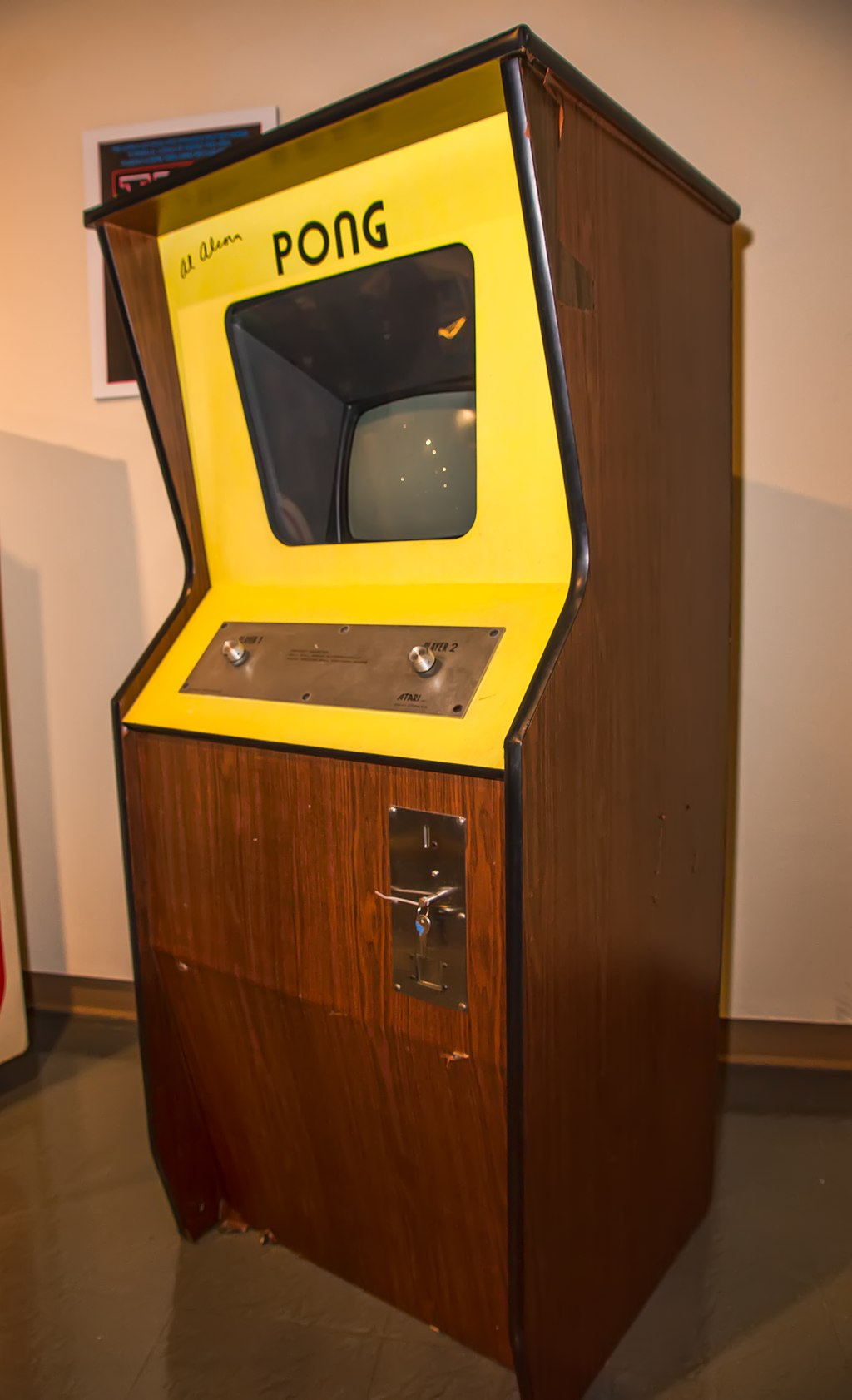
In 1972, developer Atari released one of the earliest and most classic arcade games: Pong. Pong is an electronic table tennis game featuring two-dimensional graphics to represent the paddles and balls with the score displayed at the top of the screen. Players use the paddles to hit the ball back and forth. The goal is to be the first player to reach twenty points (eleven points in the original Atari game) with points being earned when the opposing player fails to return the ball.
For our reimagination of the game, we retained the original graphics and sound effects but changed the controllers and allowed for players to be across the room. Users control the paddles by moving their arms up and down via an IMU attached to the forearm. The players could play across the room from each other using two different screens as we enabled gameplay over wifi.
An upright cabinet of Pong on display
To create this game, we used several hardware components needed to create a fully functional Pong that can be played across the room.
Raspberry Pi Pico W | The Pico W contains an on-board single-band 2.4GHz wireless interface (802.11n) which contains WPA3 and a soft access point supporting up to four clients. The onboard antenna is licensed from ABRACON and the wireless interface is connected via SPI to the RP2040 microcontroller. This was used to enable wifi communication so that the players would not have to be connected together. |
IMU controller | We used a MPU6050 containing an accelerometer and gyroscope to read angle measurements of a person’s arm in order to control the speed of a paddle. We also passed estimated angle projections through a complementary filter to ensure accuracy. |
Audio Synthesis | We used a Digital to Analog Converter to synthesize the sound effects present in the original Atari version. It plays through a headphone jack connected to a speaker. |
VGA Screen Output | Since Atari’s original game was a 2D rendition, we opted to implement the gameplay on a screen via VGA to be able to simulate the original gameplay as accurately as possible. |
Serial | We used the serial terminal to both debug and control the game. The serial terminal would output the connection state of the Picos. Additionally, we used the serial terminal to type commands to control gameplay. |
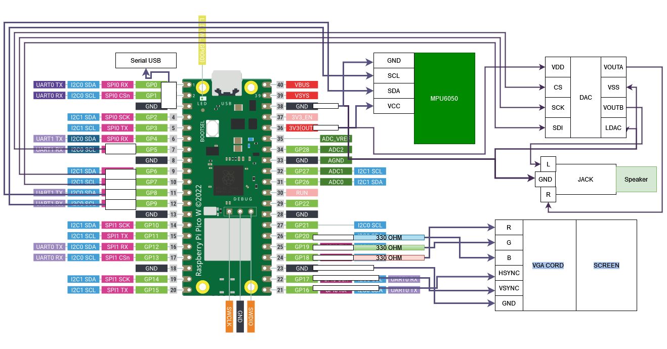
Figure 1: Circuit board schematic
The circuit above was breadboarded with the MPU6050 being connected with long wires and soldered connections to add some durability to the controller. Both Picos and controllers utilized the above setup. To set one pico as the access point/server a wire was bridged from GPIO port 4 to the 3v output.
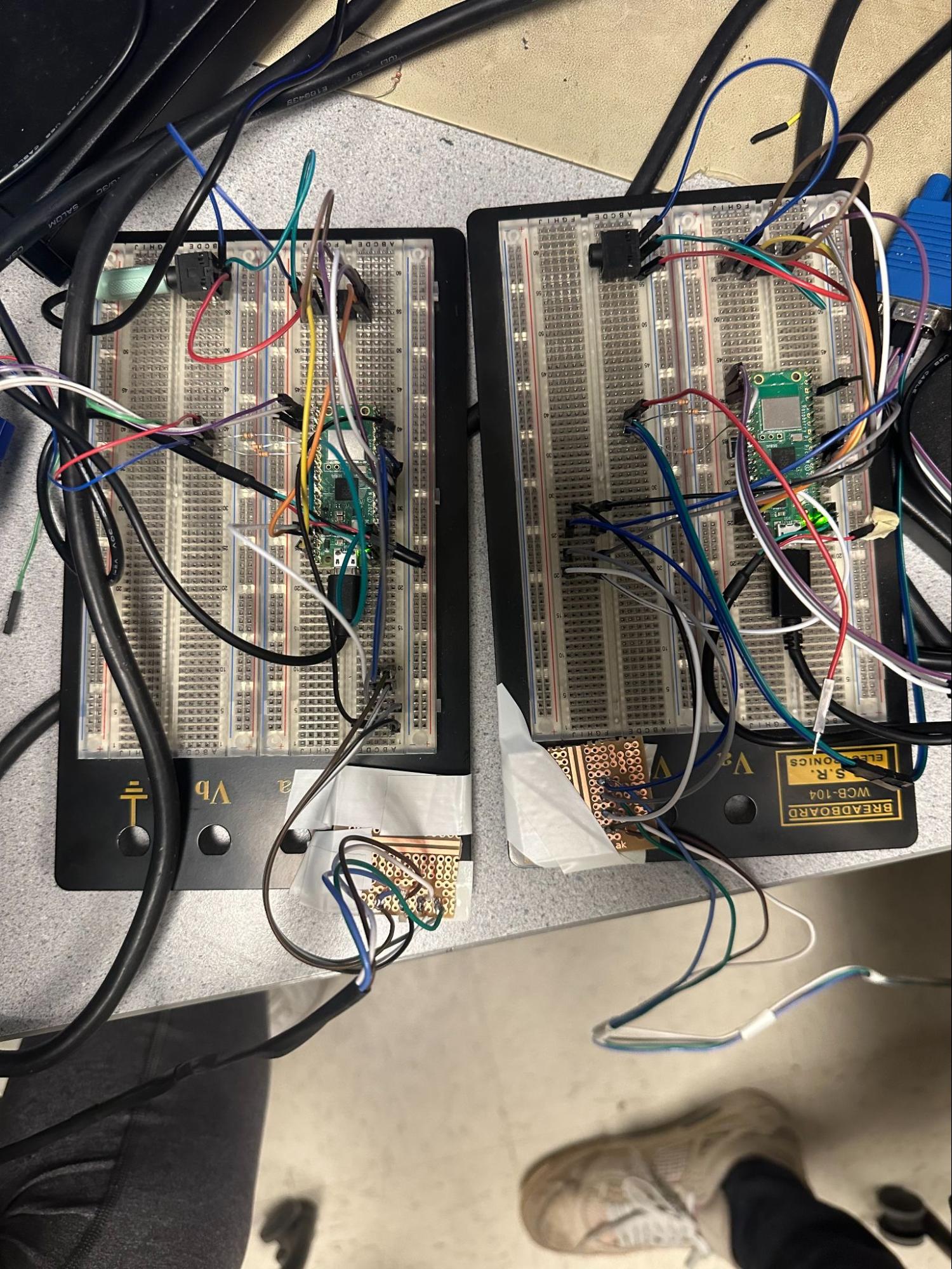
Figure 2: Physical set up of circuit board with the server Pico on the left
To execute the game, a unified file was employed across both Picos, containing all gameplay logic and UDP packet transmission and reception processes. A physical wire (GPIO to GND) connection on the Pico is configured to set one Pico as an access point and player one. For the other Pico, this connection is not hooked up and it is set as player two and the client, automatically connecting to the access point. The player one Pico runs control of the gameplay, transmitting the locations of its paddle, the ball and score to player two, while player two receives this game state and transmits the location of its own paddle. To run the paddles on each Pico, we used IMUs with each Pico calculating movement of the paddle based on a gyroscope and accelerometer. The game state on each Pico is translated into output onto VGA screens utilizing a VGA driver that allows for us to manually edit the screens pixel by pixel to generate the gameplay and broadcasts out to a VGA port. Additionally, we used the ISR to synthesize the sound effects of two different frequencies.
The game itself had four components: paddle one, paddle two, the ball, and the score which were displayed on a VGA monitor. The paddles took in the estimated angle from the IMUs using a complementary filter on its gyroscope and accelerometer. This angle would be used to set velocity which would then move the paddles up and down. We adapted Dr. Hunter Adam’s IMU demo code and VGA driver to fit our needs for this project.
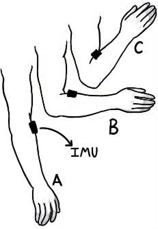
Figure 3: Arm positions for the IMU controller
The higher the angle of the arm from 90º (position C), the faster the paddle would rise to the top, and the lower the angle from 90º (position A), the faster the paddle would fall to the bottom. If the arm was held at 90º (position B), the paddle would stay stationary. The pseudo code for paddle one is provided below with paddle two written similarly using its respective variables:
if game is playing: if player 1: Read the IMU Filter accelerometer and gyroscope Calculate complementary angle arm_angle = filtered_complementary; Cap arm angle to be between 0º and 180º; // Changing y velocity of paddle 1 paddle1_vy = 0 - (arm_angle - 90) * 0.025; Cap paddle1_vy to be between accepted min and max velocities erase paddle // Cap paddle position if paddle 1 hit top of VGA: {paddle1_y = 0;} else if paddle 1 hit bottom of VGA: paddle1_y = VGA_BOTTOM - PADDLE_LENGTH; else {paddle1_y += paddle1_vy;} draw paddle
else: // player 2 erase paddle draw paddle |
Figure 4: Paddle Pseudo Code
The ball code checks if the ball hits the paddles, left or right walls, or top or bottom walls. If the ball hits the top or bottom walls, the ball reverses its y velocity and continues moving in the opposite direction. Similarly, if the ball hit the paddles, it would reverse its x direction and change the angle based on where the ball made contact with the paddle. If the ball hit the paddles at the edges, it would bounce off at a more extreme angle while if it hits the middle of the paddle, it will bounce back almost horizontally. The magnitudes of the x and y velocities are normalized to maintain the same speed even with different angles of the ball. If the ball hits the left or right walls, the opposing team would earn a point and the ball would be returned to the center of the screen and travel towards the direction of the point winner.
if game is playing: if player 1: // If hit left or right walls if ball hit right wall: erase ball ball_x = VGA_RIGHT / 2; ball_y = VGA_BOTTOM / 2; ball_vx = 0 - ball_vx; player1 earns a point; if ball hit left wall: erase ball ball_x = VGA_RIGHT / 2; ball_y = VGA_BOTTOM / 2; ball_vx = 0 - ball_vx; player2 earns a point; if ball hit top or bottom: ball_vy = 0 - ball_vy; if ball hit paddle 1: ball_vy = (paddle1_y + PADDLE_LENGTH / 2 - ball_y) / -300; Cap the ball_vy velocity to be between accepted min and max ball_vx = sqrt(BALL_V_MAG^2 - ball_vy^2); if ball hit paddle 2: ball_vy = (paddle2_y + PADDLE_LENGTH / 2 - ball_y) / -300; Cap the ball_vy velocity to be between accepted min and max ball_vx = -sqrt(BALL_V_MAG^2 - ball_vy^2); erase ball ball_x += ball_vx; ball_y += ball_vy; draw ball
else{ // player 2 if old ball in the same position as new ball: erase ball old_ball_y = ball_y; old_ball_x = ball_x; draw ball |
Figure 5: Ball Pseudo Code
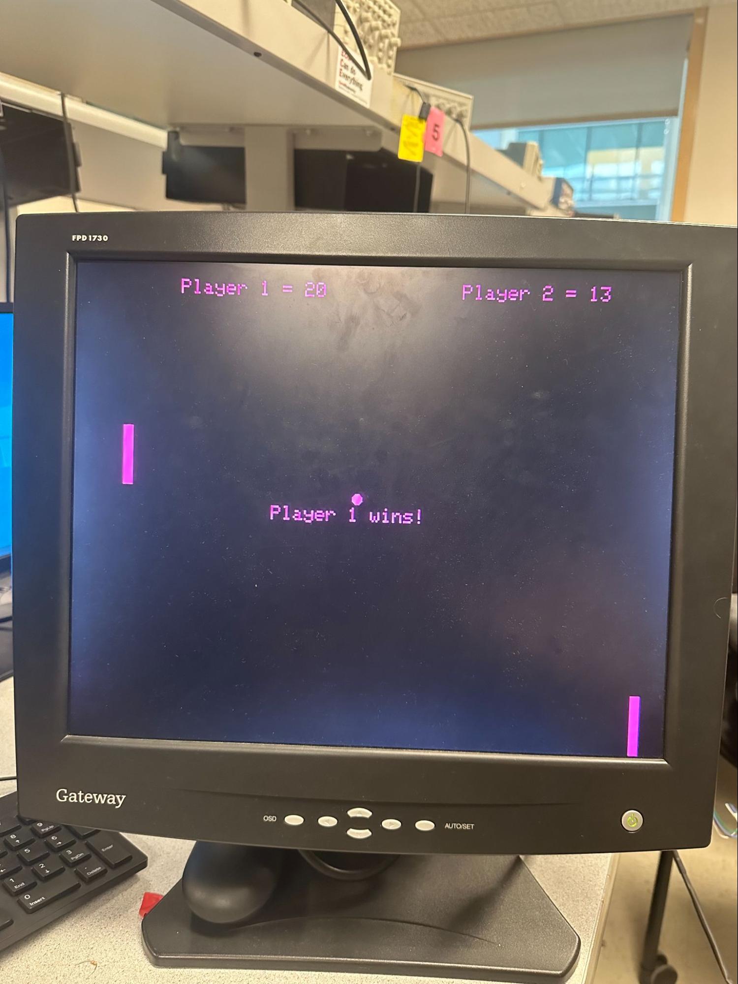
Once one of the players reaches twenty points, the play game variable will become false and freeze the game while displaying the winning player on the screen.
Figure 6: Winning screen
Our original objective was to establish intercommunication between two Picos using TCP protocols. This involved configuring one Pico as an access point and server, while the other functioned as a client. Alternatively, we considered a setup in which one Pico served as the server while the other operated as a client, with both devices connected to an external access point.
The initial plan to use TCP was scrapped due to its intricate connection structure designed to ensure the accurate and intact transmission of packets between devices, the important aspect for this case being the retry. In the context of our case, the gameplay data is transmitted at a rate surpassing the framerate, and if a packet fails to send, retrying becomes a waste of processing power which could be detrimental to the gameplay experience. There is a risk that the game state will be received out of order if a packet is re-sent (ball could flash backward to a past state). The overhead of these mechanisms also poses potential performance implications. Additionally, the TCP code examples were complex and lacked comprehensive documentation, making them less suitable for a short-time period final project. Instead, the protocol chosen was UDP. Unlike TCP, UDP has no requirements for packets to make it to a destination, and given that our primary concern is the most up to date game state, any dropped data can be ignored as it would work most effectively for our purposes.
To work with UDP, we elected to build upon Dr. Bruce Land’s Audio UDP For Web project as a base. This code used one Pico as an access point and server and one as a client through the cyw43 network driver library provided in the Pico W SDK. This facilitated the transmission of live audio from the server to the client, where it was played. To make this framework work with our design objectives, the data needed to be sent bidirectionally, and the data sent needed to be state data. To make the adjustment, the ISR that was used to generate and send (in the server) or play and receive the audio messages (in the client) was changed to instead invoke both the send and receive threads on both Picos. The data framework used was revamped to support the exchange of state data instead of a rolling sound data buffer. Below is pseudo code for this framework:
At ISR{ // Sending data_buffer[0] = some_game_state; data_buffer[1]..... // copy data_buffer into our send_data memcpy(send_data, data_buffer, send_data_size); PT_SEM_SIGNAL(pt, &new_udp_send_s); //send signal to UDP send thread
// Receive. The receive thread runs automatically when new packets arrive. This // copies the values from the received data into game state some_game_state = ((short *)(recv_data))[0]; some_game_state_2….. } |
Figure 7: Data framework pseudo code
For the client and server, the sent and received data is different.
These two adjustments were made and integers (which will be used for game state) were able to be sent bidirectionally to and from the server Pico and the client Pico. However, some issues were still present and were fixed in the integration state of the project.
To integrate the game and wireless code there were a few steps to the process.
The initial step of the integration process involved merging the source code for the VGA game with the adapted UDP communication code. The threads and main initializations from the VGA game were pasted directly into the communication code. Furthermore, all of the dependencies (VGA driver, IMU driver, SDK dependencies) had to be added to the main code. An issue arose from the hardcoded configuration of the VGA driver, specifically in its utilization of a set of DMA channels that were likely to have been reserved by the cyw43 (wifi and networking driver).To deal with this, a differently adapted VGA driver had to be used. The first option was to download a version adapted by Dr. Bruce Land to be used alongside the UDP code where the DMA channels were reserved dynamically like the cyw43 driver. This fix did not work initially, so the final solution involved configuring the VGA driver’s DMA channels to a different value unlikely to be picked up by the cyw43 driver.
Upon establishing the infrastructure, the VGA game was split into two segments, where the threads responsible for each of the game play components (paddles, ball, score) had different behavior depending on whether or not the Pico was the player1/server or player2/client. First, we had to set the game logic and rendering. This was as simple as a few if-statements where either a component would calculate game state and render, or just render. Despite the straight toward nature, challenges arose in the rendering process. A notable issue involved a pico reading a paddle or ball position from the wireless network while the past position of the paddle had not been properly cleared from the screen. This was due to our original singleplayer code integrating the erasure into the calculation of the new position. This was alleviated by storing the past position and using a stored current position value of gameplay elements and updating based on the received game state instead of just using raw game state. Next, the appropriate game data had to be sent and received by each respective Pico. The server/AP Pico transmitted the score, game status, player 1 paddle position and ball position while receiving the player 2 paddle position. The client Pico received the aforementioned sent data and sent the player 2 paddle positions.
One important decision when building the code was what threads to run on each core.
These are the threads running on core0: udp_recv(), udp_send(), ball(), and score().
These are the threads running on core1: toggle_cyw43(), serial(), paddle1(), and paddle2().
Initially, the threads were assigned across both cores based on how our original VGA game code and UDP code had assigned them. However, this unoptimized load distribution led to inconsistent timing between paddles. After this issue was uncovered it was decided that both of the paddles needed to be on the same core. Additionally, another restriction was that the toggle_cyw43() (for the wireless network driver) and the UDP send/receive threads needed to be on separate cores. serial() and score() could be run on either because they yield for a majority of the time. The ball should be on the opposite thread as the paddles to allow for easier speed tuning. The ball and the scores were put with the send and receive. The paddles were put on the other core because to maintain a smooth gameplay experience as the paddles are the main gameplay element they need to not miss frames or run slow. Send and receive are run constantly at a high rate and could cause choppiness. They were put along with the serial() thread which utilizes little function and the toggle_cyw43() thread which has a more consistent cost than the send/receive. These core assignments caused changes in the availability of compute resources. This led to undesirable changes of the speed of gameplay elements so after this was done the ball and paddles were tuned to run at the right speed.
The final stage of integration was the debug stage. During initial testing, the gameplay would halt after 30 seconds while gradually losing more and more packets. Several methods were employed to alleviate the challenge. First, we adjusted the rate of packet send/receive. This did not initially fix our issue. Second, attempts were made to debug using a one sided send and receive which also failed to reveal the underlying problem. The issue we found was that our physical setup and placement of the board combined with significant noise and crosstalk found in our test environment was the main issue. To fix this moving to a less noisy environment was the main solution, or just moving the Picos closer together.
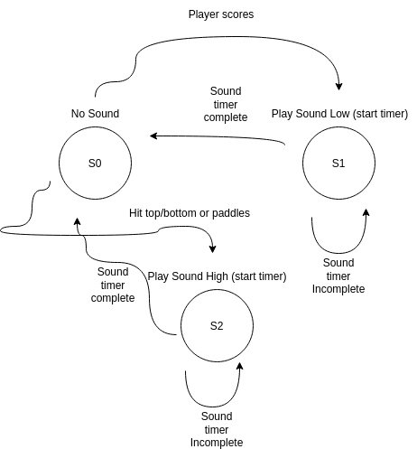
For audio synthesis our goal was to not just play sound from the server but also play from the client. To synthesize the sound we used code based on Dr. Hunter Adams’ course examples.
In main(), we generate a sine lookup table to read from.The DAC hardware is sent a certain power, and to be able to generate sound through it we need to modulate this power by a frequency. This modulation (sin wave) is created with the sin lookup table and frequency is decided by how fast we iterate through this table. The DAC signal is calculated in an ISR. The combination of the ISR frequency and the increment value allows us to control the frequency. There are two sounds we need to synthesize. A medium beep sound and a quiet beep sound. The ISR plays a sound based on a state machine that is triggered by gameplay elements. A counter in the ISR was used as a timer to regulate beep length.
Figure 8: Sound effect state machine
These states are also transmitted across the network so the client could also play these sounds.
Overall our gameplay results exceeded our expectations, although the connection range left some room for improvement. Framerate was consistent and above 30 fps (possibly 60), and if packets were dropped, it only affected the framerate and didn’t break the game. Latency was unnoticeable from Pico to Pico. Devices automatically connect to each other and all the input required to get the game to start is sent through a serial command “play” to the server Pico. To maintain a playable connection, Picos had to be kept within a foot in a noisy environment with wireless crosstalk but could be much further away in other cases. Controllers worked great and were easy to use.
When final testing was done gameplay was described as fun, difficult, and unique by TAs and faculty because of our angle to velocity based controls and smooth gameplay.
Gameplay Demo:
Note: Game is much easier when not controlling both paddles.
There were no safety concerns as there were no high-power elements in our system. To ensure comfort, we taped the bottoms of the controllers to prevent the users from the discomfort of the prongs and also solidified the base wire connections to prevent users from accidentally uprooting the controller.
We ran into a few issues when debugging. The first issue was connection issues. During initial testing, the gameplay would halt after 30 seconds while gradually losing more and more packets. Several methods were employed to alleviate the challenge. First, we adjusted the rate of packet send/receive. This did not initially fix our issue. Second, attempts were made to debug using a one sided send and receive which also failed to reveal the underlying problem. The issue we found was that our physical setup and placement of the board combined with significant noise and crosstalk found in our test environment was the main issue. To fix this moving to a less noisy environment was the main solution, or just moving the Picos closer together.
Next was VGA gameplay debugging. A notable issue involved a pico reading a paddle or ball position from the wireless network while the past position of the paddle had not been properly cleared from the screen. This was due to our original singleplayer code integrating the erasure into the calculation of the new position. This was alleviated by storing the past position and using a stored current position value of gameplay elements and updating based on the received game state instead of just using raw game state.
The results of our project both surpassed and fell short of our expectations. Initially uncertain about the feasibility of implementing game functionality over wifi, we were content with achieving successful gameplay using two standard Picos. However, through persistent efforts, we successfully implemented wifi communication within two weeks. This allowed the two players to not have any physical connections between them. Unfortunately, the Pico W proved susceptible to interference from metal and noise in the laboratory environment which meant that the players had to be in close proximity to each other to prevent lag and dropped packets. While our initial goal was to have players stand approximately ten feet apart, we had to settle for less than a foot when in the lab.
To address this issue for future projects, we propose replacing the breadboard base with one that utilizes less metal to enhance signal integrity. Additionally, hanging the edge of the Pico, where the antenna is located, over the breadboard could further mitigate the interference from the base. Our exploration also considered the potential of constructing an antenna, although this avenue would be difficult.
We credit the initial gameplay idea with Atari. The UDP connection code was based on Dr. Bruce Land’s Audio over UDP from Pico W to Pico W. The VGA driver was written by Dr. Hunter Adams. Additionally, frameworks for interacting with much of the hardware were based on examples by Dr. Hunter Adams.
This group approves this report for inclusion on the course website.
This group approves the video for inclusion on the course youtube channel.
See a full source code listing at our GitHub Repo.
Katie's focus was designing and building gameplay with the VGA and IMUs. David's focus was adapting networking code for this project and integrating it with the game to make the game functional over wifi along with audio. Once these two separate functions were completed, we worked together on two player integration and debugging.
Technical Documentation: