Zhanqiu Hu (zh338), Zehua Pan (zp74)
from IPython.display import YouTubeVideo
YouTubeVideo("https://www.youtube.com/watch?v=m4_iMseZTsA&list=PLDqMkB5cbBA6AwYC_DElkDStUdOsTuIL7&index=38", width=800, height=500)
This project implements a two-player video game through the combination of hardware and software based on RP2040 microcontroller.
From the developer’s perspective, this project is an embedded video game project designed for entertainment. In lab 2 of course 5730, the team learned the concept of boids and their behavior. During the process of coming up with ideas for the final project, the team found an interesting online game called Crowd City. Inspired by these two, the team decided to create a user-controllable video game based on what we learned in this course.
From the user’s perspective, the players could control and play the game using the two joysticks. The user interface is shown on the VGA screen. After choosing the game time on the initial interface, the players could start playing the game. During the game, each player could control a leading boid on the screen to move and infect other free boids. Those infected free boids would become members of the player’s group and the player with a larger amount of members at the end is the winner. The player should move its leading boid smartly to enlarge its group as fast as possible. Whenever the group size of one player increases and exceeds the amount of another group, a warning sound would be generated. If the time for the current game is less than five seconds, a timing sound would keep alarming until the game ends. Finally, the game ends and the winner would be shown on the screen.
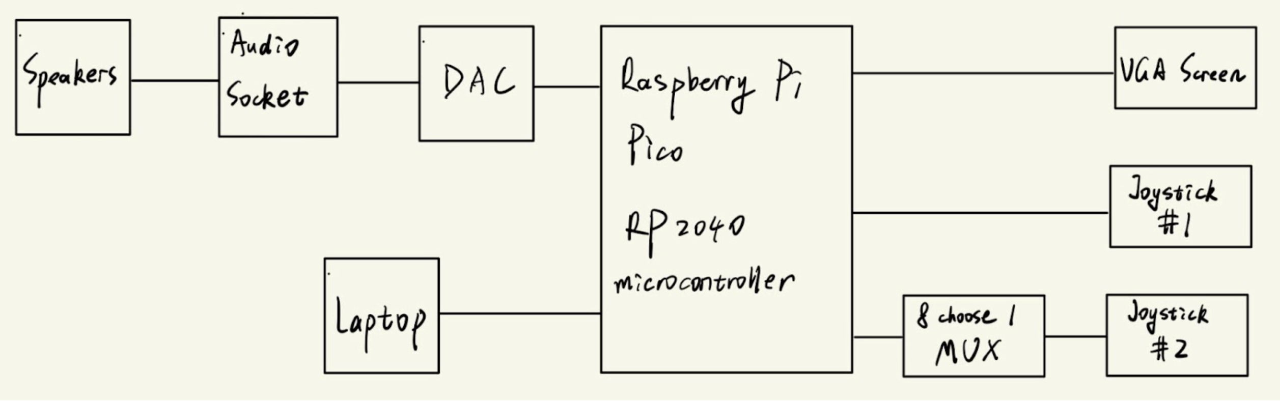
The high-level design for the hardware part is shown as the diagram in the following figure. As one can see, the core of this project is Raspberry Pi Pico development board with RP2040 microcontroller. Other hardwares are outfitted on the breadboard with physical wire. On the top-left corner, the diagram shows the part about generating sound. The team first connects Pico to the DAC converter and then connect the DAC converter to the audio socket. By this way, the digital signal generated by the Pico could be converted into analog signal and further human-detectable sound. Finally, the signal is played by the speakers connected to the audio socket. On the top-right corner, the diagram shows the part about display. In order to display the user interface of this game, the team simply needs to connect the Pico to a VGA screen. On the bottom-left corner, the diagram shows how the Pico is programmed. In this project, the team makes use of Mac laptop to write the code and program into the Pico. On the bottom-right corner, the diagram shows how the users could interact with this system. As one can see, the team first connects one joystick to the Pico directly and then insert a MUX between the Pico and the second joystick. This is because one joystick needs to use two ADC channels. Since the Pico only has three usable ADC channels, the second joystick can’t be connected to the Pico directly. Instead, the team makes use of a Mux to switch the two inputs from the second joystick and output one signal to the Pico. Since the switching delay is so small such that the user couldn’t tell the difference, this design is acceptable.
For the software part, the team defines the concepts and some initial rules for the game as the following.
Basic concepts:
Infection rules:
Following rules:
Battle rules:
Unfollowing rules:
Other rules:
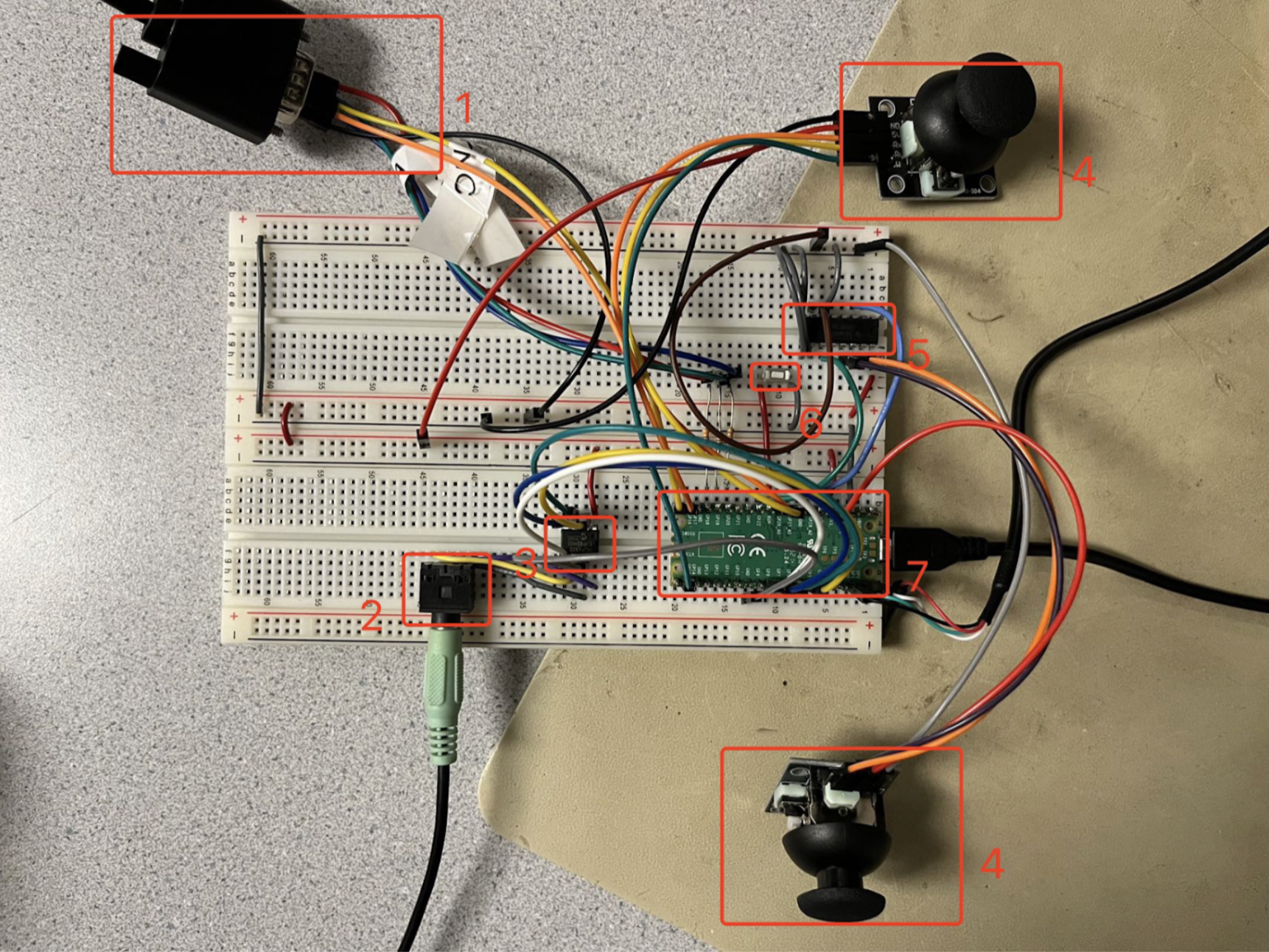
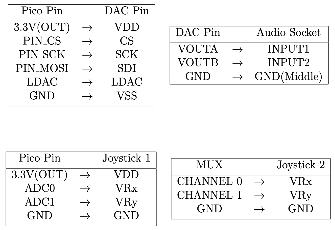
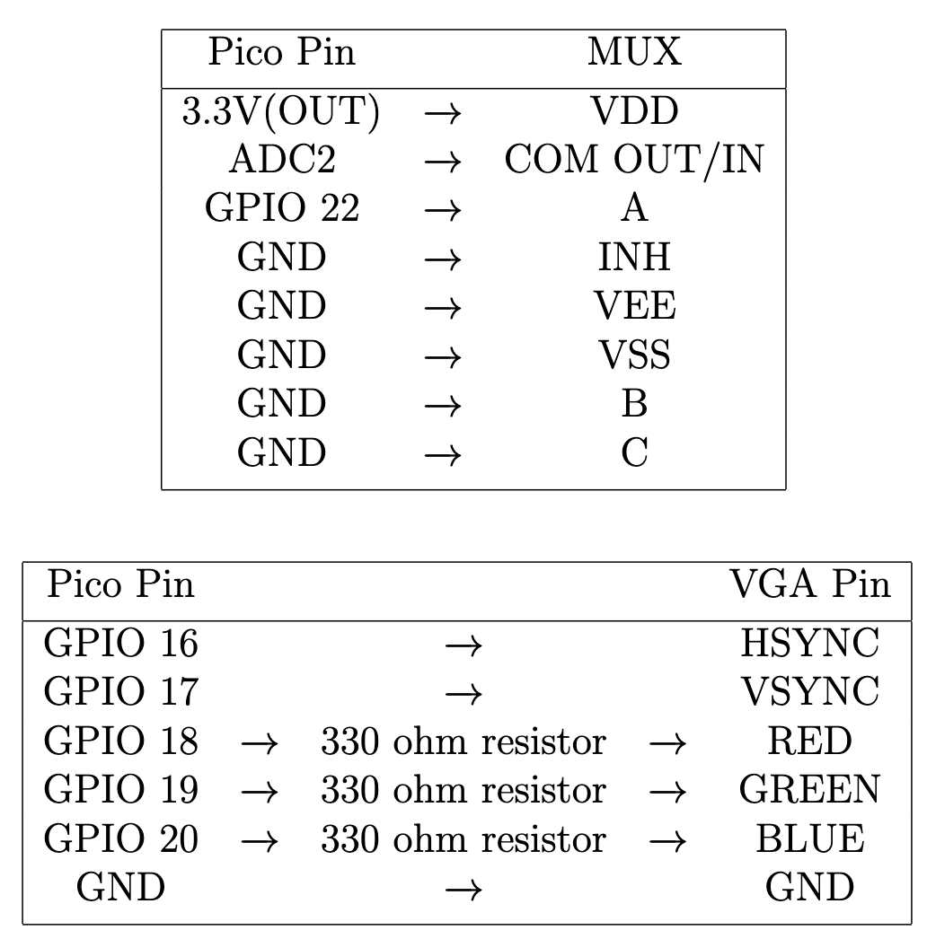
The hardware used for this project is listed as below.
The hardware setup and connection is shown in figures below. Note that the VDD of Joystick 2 is also connected to the Pico 3.3V output.
In addition, since this is the first time the team tries to make use of a MUX, the team meets a lot of issues when debugging the hardware part related to the MUX. The most important one is that the team forgets to connect the VEE and INH PIN of the MUX to the ground at first. As a result, the team observes a strange bug in the system. Specifically speaking, when using one channel input from the joystick, the output signal to the Pico is correct. But once we connect two channel inputs from the joystick and switch between them, the output signal would become some unexpected results. This is really hard to debug since the MUX does work when there’s only one channel input and the software part has nothing to do with it. The team finally figured out the bug by checking the circuit example in the MUX datasheet carefully.
In order to increase the user experience, the team adds some sound effects to the system. The sound generation algorithm is based on the direct digital synthesis of lab 1 of this course. There are three possible sound effects generated during the game. When the size of one group exceeds the size of another group by a certain amount, the Pico would generate a beep sound. Two different frequencies are designed for the two cases: the red group size is larger than the green group size or the green group size is larger than the red group size. In addition, when the remained time for the current game is less than 5 seconds, a continuous alarm sound would be generated to warn the players. The technical details come from the algorithm and logic of lab 1. The major difference is that in this project, the team only uses core 1 to generate the sound. This is because core 0 is dedicated to controlling the boids in order to maximize performance and the number of boids. Since only core 1 is used for sound generation, the system could only generate one kind of sound at a specific moment. The sound selection is controlled by the global variables in the code.
This project requires the players to use joysticks to interact with the system. There are only two joysticks connected to the system and each player uses one of them to control the leading boid. One of the joysticks is the master joystick and only this joystick could be used to control the game mode selection and game reset. When using the joystick to play, the player needs to hold the joystick in the correct direction such that the text on the joystick could be read normally. In this way, when the player moves the joystick to the left, the leading boid would move to the left on the screen. During the initial user interface on the screen, the player could use the master joystick to choose the time of the game. Once the time is confirmed, the player could press the master joystick in the middle and the game would start. After the game is over, the player could press the master joystick in the middle again to reset the game.
Before we dive into the algorithm, one should know what kind of data the joystick generates and send to the Pico. The joystick has two outputs: VRx and VRy, which correspond to the current position of the top of the joystick. The joystick uses 12 bits to encode the x and y values, which means the range of the value for x and y is [0, 4095]. When the joystick is in the normal position (not moved by the player), the output value of VRx and VRy should be around 2048. When moving the joystick horizontally, the VRx would change accordingly. When moving the joystick vertically, a similar thing happens to VRy.
From the previous sections, we know that the first joystick is connected to the Pico directly through two ADC channels. Therefore, when reading the data from the first joystick, the team only needs to collect the x and y values from the “adc_read()” function. However, when reading the data from the second joystick, the team needs to enable the switching of the MUX such that the Pico could get the x and y values. Specifically, the MUX has three control inputs A, B, and C. They correspond to the selection bits and output the data from one of the input channels. For example, when A, B, and C correspond to high, low, and low. The selection bits are 001 (CBA) and input channel 1 would be selected. In this project, we only have two inputs from the second joystick and they are connected to input channel 0 and input channel 1 separately. To enable the switching, the team only needs to use one bit. Therefore, control inputs B and C are wired to the ground. When control input A is low, input channel 0 would be selected, otherwise, channel 1 would be selected. The team makes use of GPIO 22 to control the status of control input A. Namely, when GPIO 22 is set to high, control input A is high, and the same for the case of low. In this way, the team could control the receiving data through the setting of GPIO 22 in the code. In addition, the x and y values might oscillate a little bit even though no one moves the joystick. To stabilize the data, the team shifts the data by 4 bits in the code and uses the new data for other algorithms.
Our game consists of three main states: START, PLAY, and END. We have a global variable curr_state to store the current state.
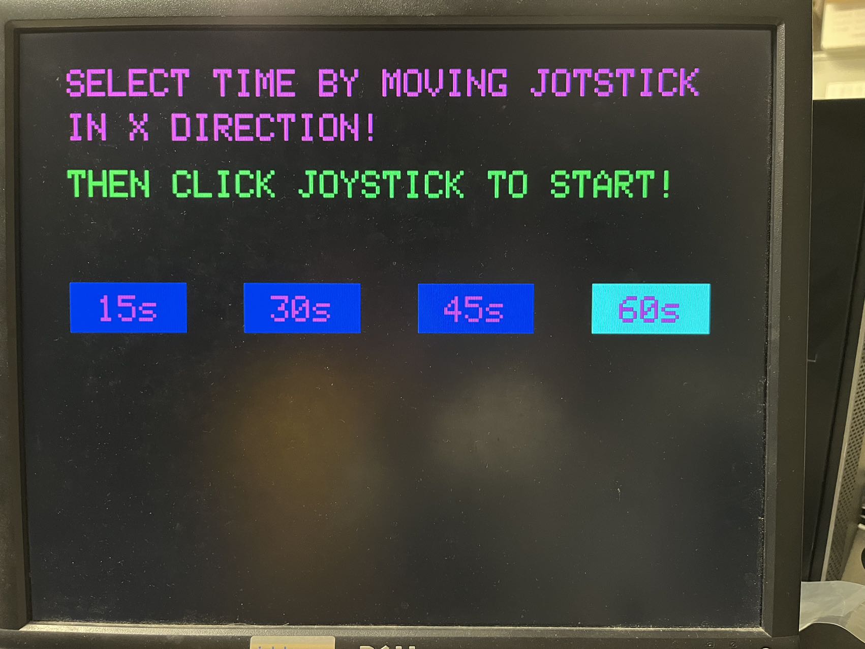
At START state, the program draws the following display onto the VGA screen. Player can move the joystick left or right to select options (time limit for the game). The options (from left to right) are denoted by integers 0, 1, 2, and 3, and the default option is 30s. We keep track of player’s current selection using a global variable. Each time the program register a movement to the left, we set current option to be: curr_opt = (curr_opt + 3) % 4; each time the program register a movement to the right, we set current option to be curr_opt = (curr_opt + 1) % 4.
After selection, the player will be able to click the button on the joystick to start the game. When the program detects a button click, it sets the current state to be PLAY, and performs some initialization.
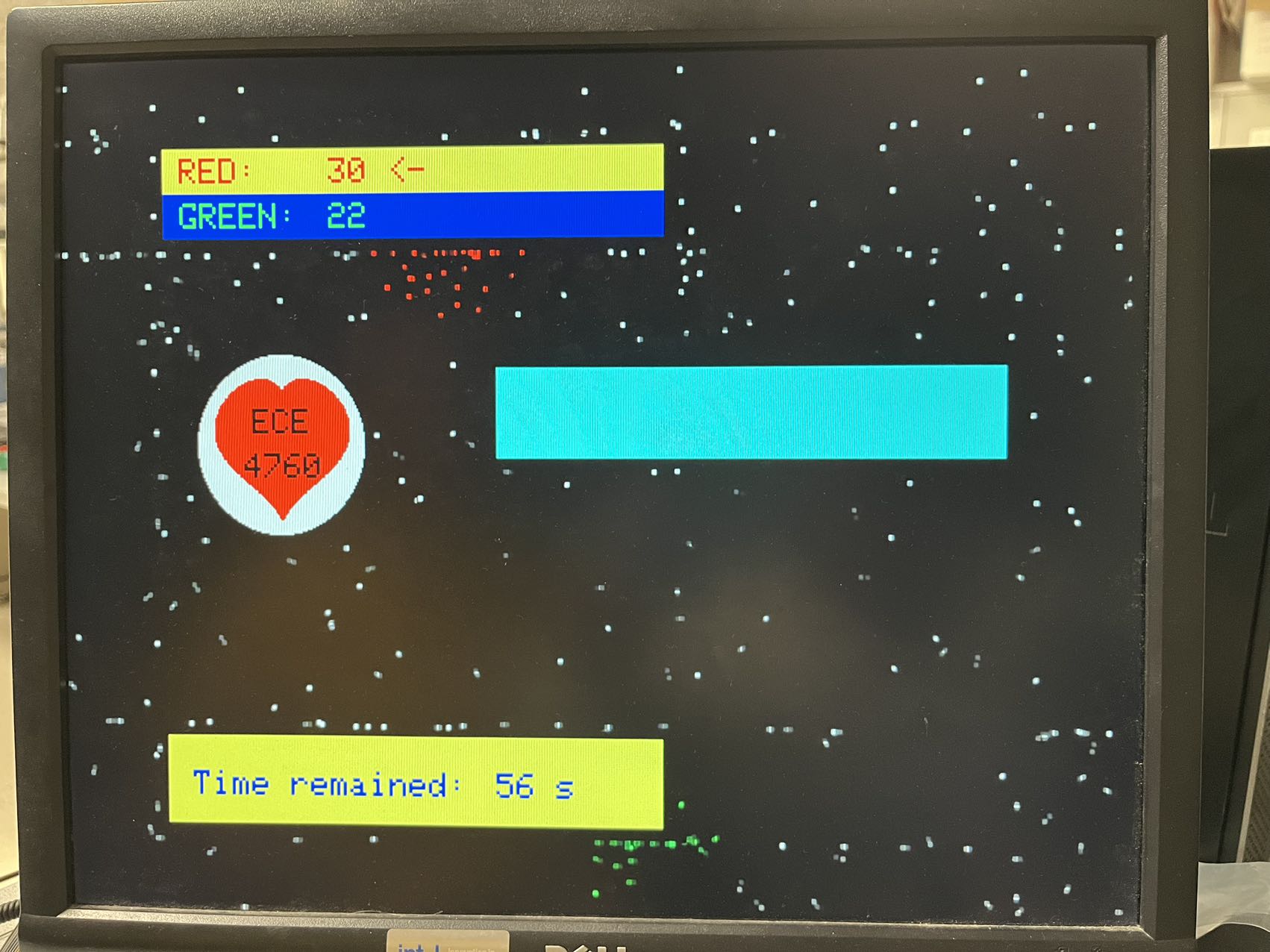
The following image shows the PLAY state. The rectangular boxes and the circle are obstacles, and scores and remaining time are printed on two of the rectangular obstacles. The other cyan rectangular obstacle moves up and down throughout the game. During state change, we first initialize the global variables used in the PLAY state, including
We also clear drawings from the START state, and draw the initial positions of obstacles and boids onto VGA screen.
At each frame, we loop through each boid and update their velocities for them to behave correspondingly to the rules we described in the first section.
If the boid is free,
If a boid is green or red, we loop through every other boid:
The following code snippets shows how we update each boid based on others. In particular, when calculating the relative distance between two boids, we defined new macros called real_x_dist and real_y_dist. This is because our game supports top/bottom wrapping and left/right wrapping. This means there are four direct paths between two boids, depending on whether we choose the path that goes across the edge of the screen. Therefore, we define the real distance between two boids to be the shortest path of the four. We also have a helper function set_boid_state that takes in the index of a boid and the state we want to set it to. The function also updates the counters to reflect the change in group size due to infection, stealing, and unfollowing.
Loop: {  fix15 close_dx = 0;
   fix15 close_dy = 0;
   // For each boid except the current boid, update the variables accordingly
   for (int i = 0; i < NUM_BOID; i++){
     if (i == boid_id) continue;
     // Compute difference
     fix15 dx = real_x_dist(*x - boid_free_x_array[i]);
     fix15 dy = real_y_dist(*y - boid_free_y_array[i]);
     int i_state = boid_free_state_array[i];
     // Check if it is in visual range
       if (abs(dx) < INFECTION_RANGE && abs(dy) < INFECTION_RANGE){
         if (i_state == -1) { // when i is free, member boids can infect free boids
           set_boid_state(i, boid_state);
         } else if (i_state != boid_state) { // both boids have color
           if (member_counts[i_state] > member_counts[boid_state]){
               set_boid_state(boid_id, i_state);// current boid with boid_id is infected
             } else if (member_counts[i_state] < member_counts[boid_state]){
               // boid i is infected
               set_boid_state(i, boid_state);
           }
         }
         close_dx += dx;
         close_dy += dy;
   }
 }
 // Add the avoidance contribution to velocity
 *vx = * vx + multfix15(close_dx, AVOID_FACTOR);
 *vy = * vy + multfix15(close_dy, AVOID_FACTOR);
We also want member boids to follow their leading boids. For each member in the group, if the boid can “see” the leading boid (i.e. within visual range), then we update its velocity as follows
*vx = *vx + (-dx0) * CENTERING_FACTOR)+ (boid0_vx - *vx) * MATCHING_FACTOR;
*vy = (*vy + (-dy0) * CENTERING_FACTOR +(boid0_vy - *vy) * MATCHING_FACTOR;
Last but not least, we update the position of each boid based on their velocity, then redraw them on the VGA screen with their new color.
We update the y position of the obstacle to reflect changes in the height of the obstacle. Recall that we have a global variable that stores the direction of movements for the moving obstacle. For the obstacle to “move” up, we erase (blacken) the bottom line of pixels and draw a cyan line of pixels of the same width above the top line of pixels, and similarly for downward movement. The obstacle starts with upward movements, and when the position of the box hits the top limit (predefined), we flipped the direction variable and start moving down. Similarly, when the position of the box hits the bottom limit (predefined), we flipped the direction variable and start moving up.
For stationary obstacles: When a boid moves closer enough to a boundary (distance to the boundary is within some pre-defined margin), it loses all velocities in the direction that’s perpendicular to the boundary and will not enter the obstacle. To prevent the boids from getting stuck in one place (i.e. having 0 speed), we assign a small velocity to it if both vx and vy are 0. For moving obstacles: When a boid moves closer enough to a boundary, it will bounce off (i.e. the velocity in the direction perpendicular to the boundary will flip sign).
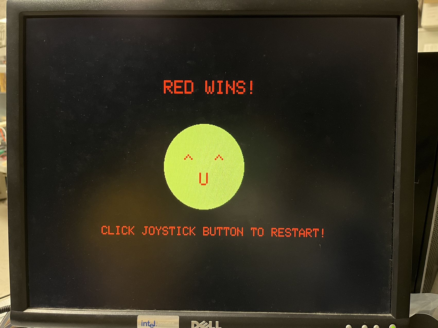
When the time exceeds the time limit, we set the current state to END state. And display end-of-game messages on VGA based on the three situations: red wins, green wins, or tie.
At END state, player can restart the game by clicking the joystick button. The program will set the current state to be START state, re-initialize the selected option to be the default option (30s), erase previous drawings, and draw prompts and option boxes to VGA screen.
In our video game, we keep our update logic to be within the time constraint so that we can guarantee 30 frames per second and keep the animation smooth. We spread workloads by using both core 1 and core 0. For example, velocity and position updates are done on core 0, and core 1 displays real-time messages (such as sizes of boid groups and remaining time) on the screen and generates sound effects. To make sure there isn’t data racing, core 0 reads and modifies global variables while core 1 only reads these data.
As described in the hardware section, we use a MUX to select and then read ADC input signals from one of the joysticks. This requires us to wait for the correct signals to be selected before we can read them. We used an oscilloscope to verify the wait time we choose is sufficient. We also verified that this wait time is short enough so that when we move the joystick, we don’t notice any lag.
At the START state, we tuned the time interval between two joystick registration, so that when we move the joystick left or right, the selected option box changes smoothly but not too quickly. We asked our friends to play the game and fixed some issues based on their advice. For example, we changed the color and size of some objects displayed on the VGA and added the arrow next to the member count.
We make sure our design is safe by using 3.3V output on the Pico board to power all of our hardware components, instead of using any external voltage course. This eliminates the risk of accidentally burning the Pico board with high voltage. For the components to function as expected, we also checked all components in our system to make sure they are properly grounded.
Overall, our design meets our expectations. The movements of boids and their interaction matches the rules we specified when we started this project. We added different obstacles to increase the complexity of this video game. We also implemented the sound effects and starting and ending states to make the game more playable. We found the video game to be very interesting, our friends also had fun playing it! We used the starter codes for lab 1 (for sound effects) and lab 2 (for displaying boids on VGA), and we also designed our following and avoiding logic based on lab 3 instructions.
"The group approves this report for inclusion on the course website."
"The group approves the video for inclusion on the course youtube channel."
| Name | #Item | Price | link |
|---|---|---|---|
| Raspberry Pi Pico | 1 | $9.99 | link |
| Joystick | 2 | $6.29 | link |
| CD4051BE MUX | 1 | $0.79 | link |
| Breadboard | 1 | $4.20 | link |
Zehua Pan(zp74): partial hardware setup and debugging (e.g. sound generation part, VGA and UART debugging, general design), sound effect algorithm, joystick algorithm, basic boid algorithms (e.g. initial moving, position and velocity update, infection).
Zhanqiu Hu(zh338): partial hardware setup and debugging (e.g MUX connection and debugging, joystick wiring), joystick update, advanced boid algorithms (e.g. layout design, adding obstacles, boids colliding onto obstacles, three game states, dynamic text update, unfollowing rules, bouncing rules, and battle rules).
ECE 4760 Lab 1: https://vanhunteradams.com/Pico/Cricket/Crickets.html
ECE 4760 Lab 2: https://vanhunteradams.com/Pico/Animal_Movement/Animal_Movement.html
Original Crowd City game: https://crowdcity.io/