ECE 5730: Digital System Design Using Microcontrollers
Final Project: Water Particle System Animation Implemented on RP2040
Weilun Wang (ww474), Yue Wang (yw2359), Yibo Yang (yy796)
1. Project Introduction
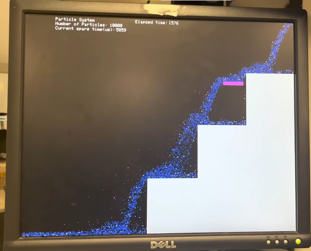
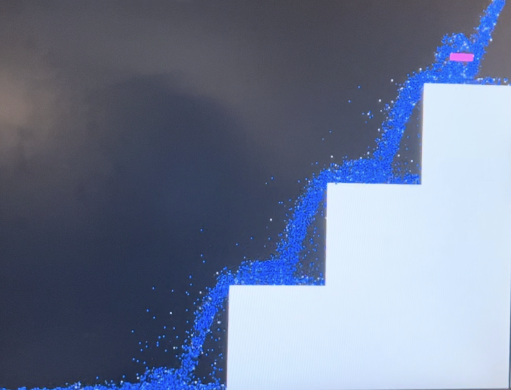
This project aims at simulating a realistic waterfall animation with user interaction. We’re interested to learn how a particle system works and see how realistic it can be. We chose to build a waterfall that flows downstairs and added a moveable bar controlled by the user to bring some interactivity to this system. Here is the Youtube link of the demo video.
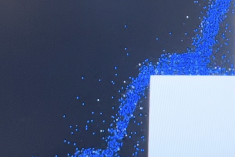
Fig 1.Waterfall Simulation
2. Design Overview
2.1. Rationale
The idea for this project came from Hunter’s possible project list demonstration. We found the particle system topic very interesting and attractive during his introduction. The particle system can be so versatile that it can realize so many different visually authentic effects like fireworks and candlelights. This kind of authenticity is achieved through a large number of pixels that can reveal the details of these effects. Based on experience, considering that the particle system involves less interactivity since the overall effect won’t change greatly as time passes by, it is possible to achieve a great number of pixels displayed on the VGA screen while maintaining appropriate FPS.
After talking with Hunter and Bruce about this idea, they suggested that we can make the system more visually appealing by animating some natural-world effects that people have been quite familiar with so that it's easy to tell whether the animation is vivid. Combined with all these thoughts, we felt that it would be a great idea to simulate the waterfall, just like the Ithaca Fall, which is a water particle system. To add more interactivity to this system, we designed a stair on the right side of the screen so that after the water falls from the left top corner, it will reach the stairs and then flow down the stairs.
2.2. Background Information
A waterfall is a point in a river or stream where water flows over a vertical drop or a series of steep drops. It is made up of countless water molecules, each of which behaves independently and interactively. Each particle can be regarded as ‘independent’ before it hits and is blended with other elements, and the process of fusion is where the interactivity exists. Besides, when taking interacting with external system objects like stones at the bottom of the waterfall, or the stairs in this project, many other important factors are playing important role in making the scene around that area appear to be chaotic. With the naked eye, we may observe that there are boiling masses of water at the bottom of the waterfall, and it seems to be very powerful. So how does this happen?
The whole animation process can be divided into two main parts, which are the free fall in the horizontal direction and the interaction of water particles with stairs. The free fall process for each particle will follow the physical rule, meaning that each particle will have an original horizontal velocity, given the characteristics of the realistic waterfall, but zero vertical velocity at the beginning. With it falling freely in the air, due to its motion, it will gain kinetic energy from gravitational force(which is the force that pulls all the objects towards the ground) that is doing work on it. The work of a gravitational force is a form of energy transformation since While the waterfall's vertical velocity increases and its height decreases, so the kinetic energy increases and the gravitational potential energy decreases, and this happens in a way that the total energy is always the same. After the particle hits the stairs’ surface, since it is not an elastic collision and friction does exist, there will be some energy loss every time that the particle bumps onto the surface. Given that the stairs have both vertical and horizontal surfaces, we used two different resistance coefficients to calculate the energy loss. This will be introduced in detail in the particle motion simulation part later.
2.3. Software Overview
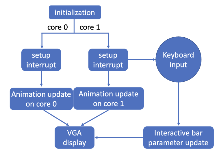
As we can see from this flowchart, the waterfall simulation system starts with the initialization, including standard input/output and VGA, then core-0 launches core 1. Core 0 is responsible for the interrupt setup as well as the update for even-number indexed water particles, while Core 1 is responsible for odd-indexed ones. Also, the serial input handler is set to run on core 1, so it can take user input from the serial interface to change the parameters for the user-interactive bar and control its position.
Fig 2.Software Diagram
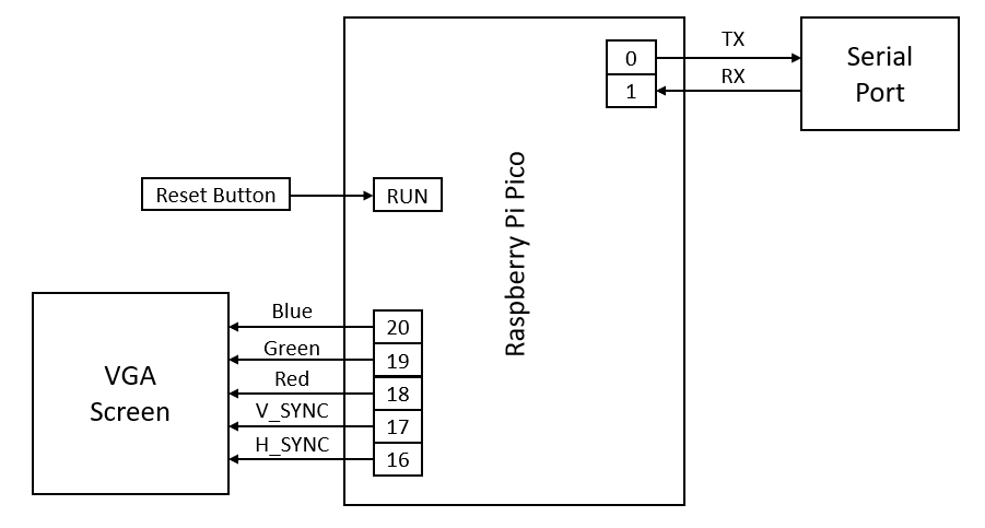
2.4. Hardware Overview
Only two parts of hardware are involved with the system: the VGA driver and the UART serial input/output. The VGA driver is implemented by the PIO state machines, used to display the simulated waterfall, and the UART is used for debugging and user input.
Fig 3.Hardware Diagram
3. Detailed Design
3.1. Hardware
3.1.1. VGA Interface
We adopted the VGA interface developed by Hunter[1], which uses the three PIO state machines to drive a VGA screen. Three bits are used to represent one pixel, and we hold all the information for 640*480 pixels in a large memory, which the DMA channel will read data from and transport to the PIO state machines for VGA output.
3.1.2. UART
The UART is used both for printing debugging information as well as the user interface. Since this system requires a constant frame rate of the simulation, the serial read and serial write operation must not block the program. Therefore, we’re using the ProtoThreads for Pi Pico RP2040[2], which defines the non-blocking version of serial read and serial write. The thread for read and write yields until the UART channel is readable/writable, instead of outputting all characters at once or checking for “enter”, so to avoid blocking other important threads.
The logic for using the UART to control the small block in the simulation is a little different. Instead of reading the whole string which ends with an “enter”, we want the block reacts whenever the user puts a character of “A”, “W”, “S”, or “D”. In this case, we simply use a uart_getc() when the UART channel is readable, and then change the block’s position according to the input character. In this way, the reaction becomes more direct and instant.
3.1.3. Mouse
I tried to develop a PS/2 protocol to add a mouse to our system using the Programmable I/O since this would be more instinctive than simply using the keyboard. I managed to build up the open collector circuit needed for the interface and wrote the basic structure of the PIO assembly program, but it takes way longer than I thought it would. So I just dropped this and used the UART instead. Maybe I would continue on this at a later time.
3.2. Software
3.2.1. Particle System
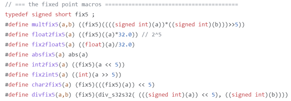
The simulated waterfall is a particle system with a very large number of particles to make it as realistic as possible. Every particle has four characteristics: x position, y position, x velocity, and y velocity. We created a struct in C that holds these four values for each particle. Since all the data is preallocated, we had to keep the struct as small as possible to create as many particles as possible. The size of the screen requires at least 10 bits (29 < 640 < 210) for the position, therefore we defined a “fix5” data type: 11 bits for the integer part and 5 bits for the fraction part. Related calculations are defined as macros as shown in Figure 4.
Fig 4.Macros define for calculations in the “fix5” data type
In this way, the largest number of particles that we achieved is 12000, which is quite enough to simulate a realistic waterfall.
3.2.2. Particle Motion Simulation
To correctly simulate the motion of particles according to real-world physics rules, we design the motion update function such that it includes the following feature:
Air-drag in the horizontal direction.
Air-drag in the vertical direction.
Gravitational acceleration in the vertical direction.
Restitution coefficient when a particle bounced back from a collision with a wall.
After every collision, the particle switch color from white to blue or the other way around
We started the design by assigning real-world values to the system such as using 9.81 m/s^2 for gravitational acceleration and 0.67 for air drag in both directions. But since the VGA screen is limited at 640 x 480, all these real-world values do not simulate the particles realistically, therefore we started to tune our system.
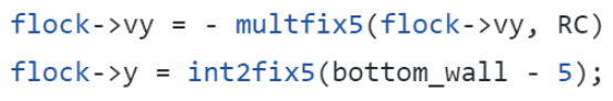
For the vertical speed, we set it up such that it always has a downward acceleration but also an upward air drag proportional to the current vertical velocity as follows where G30 stands for gravity factor and CD stands for Coefficient of Drag:
After testing we found that to simulate the gravity and air-drag properly on the VGA screen, the best values for G30 and CD are 1.1 and 0.1. With this, we can simulate free fall motion for the particles.
For the horizontal velocity, it should only include an air drag in the opposite direction of the current horizontal velocity. Therefore we set up the velocity update as follows where CDx stands for Coefficient of Drag in the x-direction:
Originally, we were using the same drag coefficient for both horizontal and vertical velocity. But unlike vertical velocity, there is no constant force like gravity acting on the particle in the horizontal direction therefore using the same drag coefficient will cause the particle slows down in the horizontal direction way faster than in the vertical horizontal and even stop moving at the middle of the screen. Therefore for CDx, we use only 0.03 to represent the horizontal air drag.
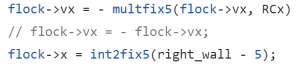
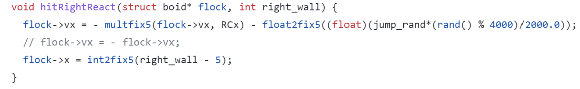
For the collision cases, we only need to consider 2 cases which are collision with a horizontal wall and collision with a vertical wall. To simulate this collision properly, we set up the position update as follows. If there is a collision between a horizontal wall:
RC stands for restitution coefficient to represent the energy loss from an inelastic collision. After tunning, we found RC 0.8 can best simulate the bouncing. And to make sure after we reverse the velocity, the particle won’t go across the boundary if the previous velocity is too high and there is not enough time for it to reverse the motion, we set its position 5 pixels above the boundary.
Similarly, if a collision between a vertical wall occurs, we set up the position update as follows where RCx stands for restitution coefficient in the x-direction.
The reason for us using two different RCs for vertical and horizontal is also just to compensate for the lack of horizontal forces for the particle system. After testing, the best value we found for RCx is 1.1. We understand that it’s physically impossible, but with such value, the simulation looks the most organic and visually correct. As a computer graphics project, we decided to keep this value since ‘If it looks right, it is right! ’ for graphic projects.
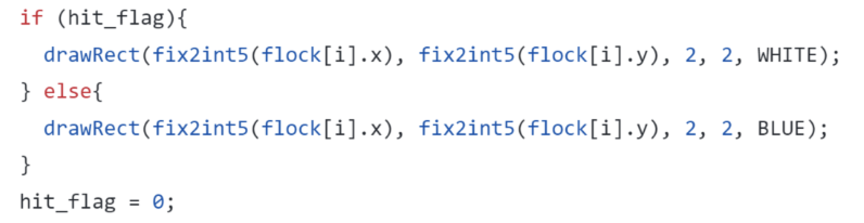
The intention of switching particles' color after every collision is to simulate the actual splashes in the real world from water hitting each other and the obstruction. We step up a color flag for each particle in each frame to check if the particle has any collision within this frame’s motion update, and we redraw that particle according to the color flag to create the sense of splashes as follows.
The color switching did help people to better see the simulation and think of it as a waterfall.
Fig 5.White and Blue color representing splashes
3.2.3. Looping Waterfall
After we finished the dynamic update method for all the particles, we start defining the boundaries of the VGA screen to form a proper playground for the particle system.
Fig 6.Particle system boundary setup
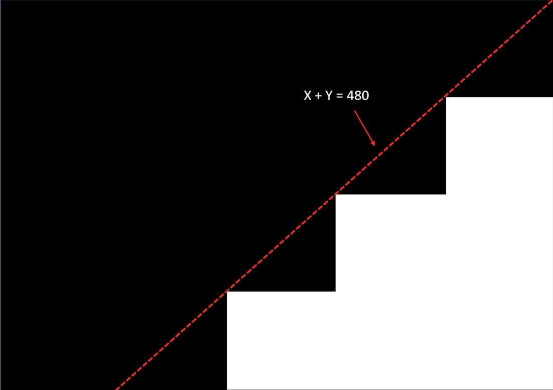
We set up a 3-step stair for the waterfall to run down, each step has a height of 120 pixels and a width of 120 pixels. The water starts from the right upper corner and when they reach the left side of the screen, they will be teleported to the right upper corner again with new initial values. By doing this, we form a loop system where the waterfall will continuously run down the stairs. We defined the boundary detections as follows and use them to update each particle under different circumstances.
And for the cases when it hits the bottom boundary:
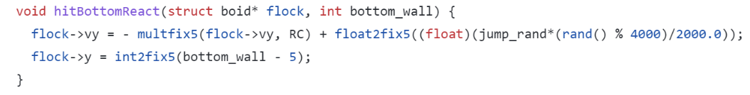
When the particle reaches the left side of the screen:
3.2.4. Boundary Detection
Since this structure we are setting up is a stair, for the particles to properly update their velocity, each step of the stair would have its own right wall and bottom wall. This means our velocity updates must change according to the particle position. We have come up with a method to simplify this process, by checking whether the sum of the x and y position of each particle is larger than 480 first, we can identify all the particles on the right side of the screen.
Fig 7.Primary boundary check logic
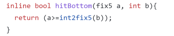
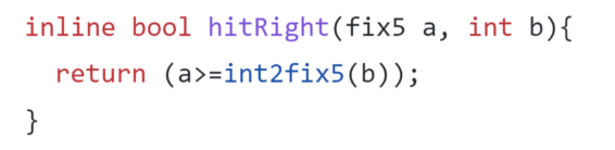
We then check the individual x and y positions to locate which step are they at and assign them to the proper right and bottom walls. We design the detection function as follows.For the bottom detection:
For the right wall detection:
By checking all the walls on each stair step, we are able to update the position of each particle accordingly.
3.2.5. Boundary Conditions
Fig 8. Boundary issues
The boundary conduction can be very tricky in this project. Upon observation, we noticed that it was very easy for particles to exceed the boundary, once this happened, they will eat up the stair step. Although the stair steps will be redrawn in every frame, having the stair step get eaten up by water is unrealistic. We think the bottom wall getting eaten up is because of the velocity update when the particle hits the boundary too fast, flipping its direction with some energy loss can not reverse the direction of the motion immediately, so it might go through the boundary and comes back a few frames after. To fix this problem, we added to the Hit-bottom_react such that when a collision occurs, not only do we flip the direction, but we also lift the particle up a few frames so that it can change its velocity in a couple more frames and prevent it from hitting the wall.
A second question is that at the corner of the stair step, particles might be at the boundary of switching dynamic updating rules every frame. This causes the corner gets eaten up almost constantly. To solve this problem, we added a few more operations when we check the position of the particles. When the particle is within the 10 pixels * 10 pixels squares on each stair step corner, we won’t draw that particle. And when they left those squares, we redraw them again. This will result in some particles suddenly disappearing from the screen and suddenly reappearing after the square, but since we have 10,000 particles running at the same time, people can’t notice that effect and we solve the problem of stair step getting eaten up.
3.2.6. Randomness
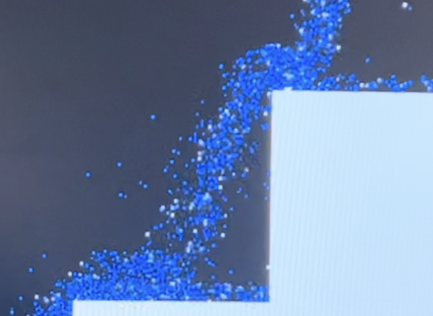
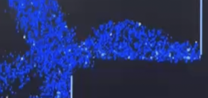
The key for this simulation to look real is to introduce randomness into the system to simulate all the different factors from the real world we can’t simulate directly such as wind, viscosity, surface roughness, and even quantum entanglement. As a result, we were trying to add as much randomness as possible into the system. Firstly when we generate all the particles, we give them a random location at a 7x5 pixel box at the right upper corner and also a horizontal velocity of 3 pixes/s and vertical velocity of 0 both with randomness from -1 to 1 with a difference of 0.001. This allows all the particles to come out from the jet with about the same velocity but randomly spread out just like a real-world diffuser. Also, we introduce the same randomness whenever a collision happens to the velocity, and by doing that we are able to create splashes like the following picture shows.
Fig 9.Splashes generate from adding randomness
By doing this, our waterfall simulation looks more realistic on the VGA screen.
3.2.7. User Interaction
The user can type “A”, “W”, “S”, and “D” to move the bar towards the left, up, down, and right of the screen. You can also type “X” and input a number to set the width of the bar. The bar’s position variables are predefined just like the struct for each particle and are subject to change by the user. Collision detection with the bar works similarly to the walls, but for simplicity, we only detect the upper boundary detection with the particles and neglected the side boundary since it’s easy to cause bugs in the program. As long as we keep the bar thin enough (about 4 pixels), everything would look just fine.
3.2.8. Bugs We Didn't Fix (It's a feature!)
Since we are updating all the particles according to their location from their last frame, there will be cases where the particle is right on the boundary, especially for 10,000 particles, this happened more often than we expected. For these cases, we are not able to assign the direction of the velocity unless we store their old positions and do an interpolation for every frame. However, while we were debugging and trying to fix it, we found out that if we assign those particles to move right in those cases, some of them create a nice hydraulic jump at the vertical wall and some of them stay on the horizontal wall. These two effects somehow demonstrate a similar effect like having particle-particle interaction accounted in the system, which actually helps us to simulate the animation more realistically, therefore we decided to keep it as it is.
3.3. Reference Codes
We did not use any code that is involved with existing patents, copyrights, and trademarks.
4. Results
4.1. 10,000 Particles
At the beginning of the project design, we were planning to design the method such that it also includes particle-particle interaction. But since our system is simulating 10,000 particles, we need to calculate all 10,000 particles’ positions for every frame of the simulation. To incorporate the particle-partical interrection, each particle would need the location of other particles, and going through all of them under 1/30 s is impossible due to the computational speed of RP2040.
4.2. Interactivity
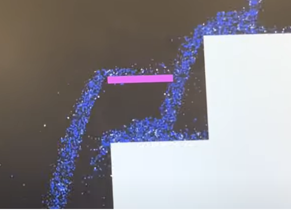
The user interacts with the system by moving the bar to change the flow of the waterfall. The bar can catch some water and split the water into two flows (as shown in Figure 10).
Fig 10.Water is split into two parts by the bar
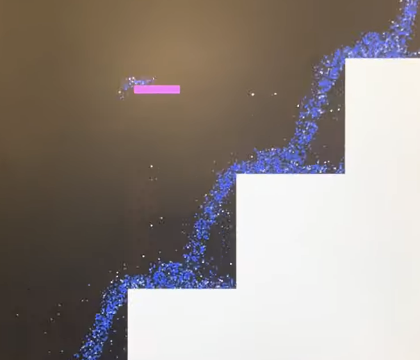
The bar can even carry some water to the left (as shown in Figure 11) for a while since the water has about the same speed as the bar when the user moves it.
Fig 11.Water carried by the bar to the left
4.3. Does It Look Real?
It looks pretty convincing as a waterfall. The waterfalls due to gravity, bounces on the ground and splashes, some water stays on the stair, and the collision between the moving bar and the water looks realistic. We simulated the physical model of the system very well, but we don’t have much of a color choice to make the water look more natural. We simply set the initial particles as blue, and randomly change some particles to white when it hits a wall so to simulate a splash. We didn’t go deep into the color aspect of the waterfall.
5. Conclusions
In general, the result of this project meets our expectations, but it is not exactly what we planned at the beginning. We encountered a lot of difficulties when trying to develop the PS/2 protocol for the mouse, thus we didn’t realize to use the mouse to initiate the start point of water fall on the screen, or to drag the interactive bar. Though these expectations weren’t met, we still used the keyboard input as a substitute and achieve similar functionalities. This is the lesson that we have learned. Maybe next time we will have more checkpoints during carrying out the project so that we can have a clearer understanding of the schedule or make changes accordingly if necessary.
6. Appendix
6.1 Permissions
The group approves this report for inclusion on the course website.
The group approves the video for inclusion on the course Youtube channel.