Spatial Audio Murder Mystery
ECE4760 Project
By Minjung Kwon(mk2592), Amy Wang(yw575), and Ann Xu(asx3)
Introduction
By using the Raspberry Pi Pico, this project implements spatial audio into a fun and interactive murder mystery game. We generated self-recorded audio and passed it to headphones while applying a spatial audio algorithm to the input audio. To the headphone user, the audio appears to be coming from the specific direction the user chooses with the joystick. The goal is to closely mimic how sounds in real life reach our ears, depending on where the sound is coming from.
High Level Design
Spatial Audio
Spatial audio simulates sound localization, the ability to detect where a sound is coming from and how far it is, to “trick” the human brain when listening to input audio. For example, spatial audio would make you think someone is speaking to you front-on or someone is speaking to your left even if you are alone and not moving. The human brain is very good at detecting where a sound is coming from and here, we artificially created this effect using spatial audio. Basic versions of spatial audio is already a feature that many tech companies use. For example, when listening to the song “Left and Right” by Charlie Puth through Apple headphones, you would be able to hear the music as if it is solely coming from your left or your right.
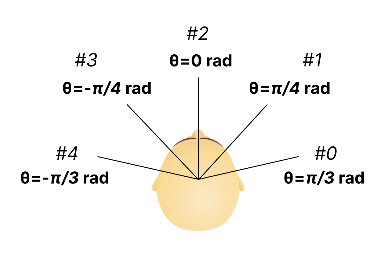
We thought this would be a cool final project idea because of the increasing innovation in headphones and audio technology. Therefore, being able to build a simple version of spatial audio would be a good introduction to some of the more complex algorithms that are being developed today. Because some of the past projects in this class also implemented spatial audio, we wanted to not just simply implement spatial audio but also use it as a main component to a game. In the audio game, sound/voices would come from the 5 directions illustrated below.
Game Design
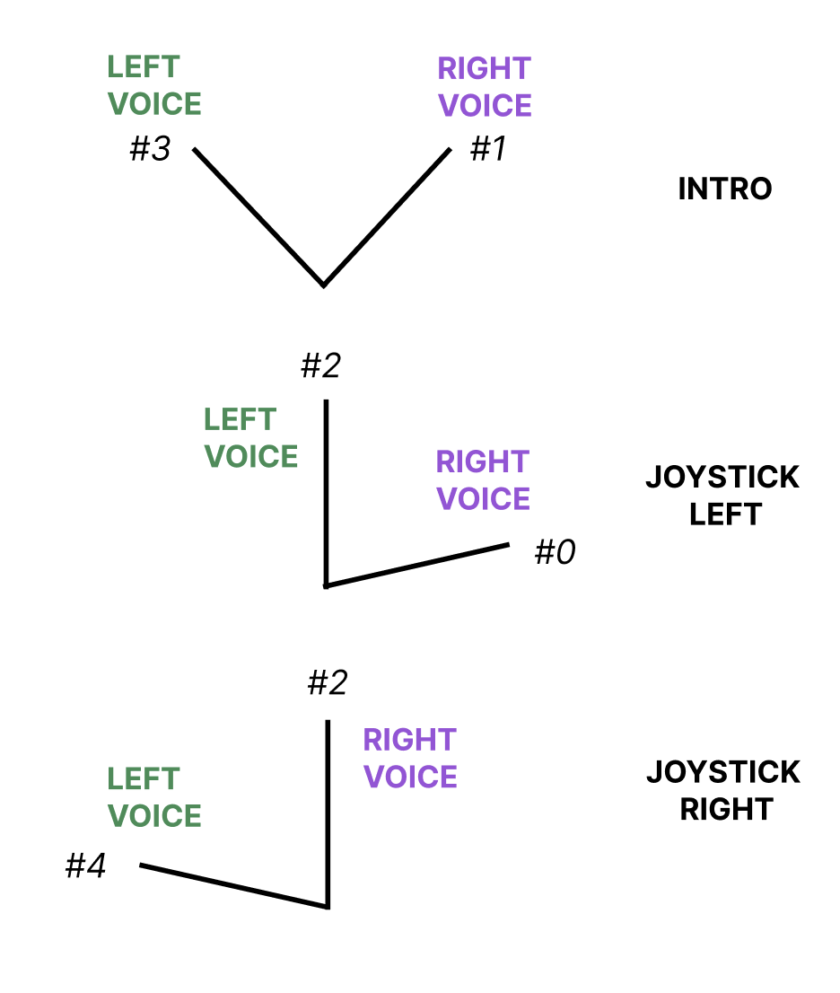
The game is single-player murder mystery game that has no visuals and is solely dependent on audio. Set in a spacious mansion, the game involves 3 rooms and 6 characters: Mr. Hopper(Head of the house), Ethan(Brother), Clara(Sister), Liz(Maid), Francis(Gardener), and Sydney(Cook). The victim is Mrs. Hopper(Mr. Hopper’s wife). The game begins with a short introduction that briefly explains the game structure. This introduction specifies the spatial audio nature of the game and encourages the player to use the joystick to choose who to focus on and who to have in the background. The joystick is important because each of the 3 rooms contains 2 of the 6 characters, each speaking their side of the story. If the player does not choose one of the 2 players to focus on, they will only be able to hear muffled voices coming from both. Figure 3 below shows how the player will perceive the direction of both voices when they use the joystick to choose a specific voice.
At the end of the game, the player must make a guess on who the murderer is. Because there are 3 rooms, the player can only focus on 3 voices per game. This means that the player is only exposed to 3 individual stories per game. Thus there are 2^3 ways the player can hear the stories, giving each player a unique playing experience.
Basic Structure
This is a general overview of the structure of the project. A detailed description of each part, both hardware and software, are described in the “Hardware”, “Software”, and “Results” sections below.
Sound, analog data, is outputted to the headphones via a headphone jack, yet the algorithms that make the input audio into the desired spatial audio is done with software and therefore with digital data. This means that a Digital-to-Analog converter is necessary. We used the DAC circuit and output audio jack circuit we built in Lab1 for the cricket synthesis as the general purpose of the circuit remained the same: to transform digital output from the Pico to analog input that can be heard when a speaker/headphones is plugged into the audio jack.
Because we wanted to focus on the spatial audio algorithm, we began the project with no input audio to the Pico. Rather, we synthesized beeps by using direct digital synthesis similar to how we created beeps in lab 1. We tested our algorithm with the beeps and this helped us gain a better understanding of how the algorithm works and how we can manipulate the algorithm so that the beeps are coming from the desired angle.
We first began user interaction with the audio by using UART transmission so that the user could type in the desired direction, illustrated above as #0-#4, on PuTTY. This was only done because the joystick we ordered did not arrive yet. This transmission and receival of data between the two devices (lab computer and Raspberry Pi Pico) was done through the two dataline that exist on the UART channel. The connection between the two devices were done by using a USB type A plug breakout cable with female jumpers. The connection to the lab computer was done by simple plugging in the USB type A end. As shown in the block diagram below in the “Hardware” section, the connection to the Raspberry Pi Pico was done by connecting the Tx wire, which receives data from the computer to GPIO 0 (pin 1), the Rx wire, which transmits data to the computer, to GPIO 1, and the ground wire to GND (pin 3). The power wire was not connected to anything as it was not needed.
The joystick was then used to control the direction of the output audio. The Pico would read the x and y positions from the joystick and if both were within a certain range then it would mean the user has chosen 1 of the 5 directions.
The game audio was inputted through two audio jacks (because two people are talking at the same time) that were connected to a simple voltage-level shifter circuit. This voltage level shifter circuit was necessary because we needed to adjust for the voltage range of the Pico’s ADC inputs (0 to 3.3V). We had two input audios, one character talking for the left ear (controlled by core 0) and one character for the right ear (controlled by core 1). Both audios used Pico’s ADC pins, ADC 0 and ADC 1 respectively. The ADC pins were necessary because the input audio was analog data but the Pico does the spatial audio algorithm on digital data.
The joystick needs two ADC pins and the game input audio also needs two ADC pins, but the Pico only has 3 ADC pins! We decided to let the joystick only use one ADC pin, so the joystick was limited to the x direction.
Throughout the entire process of completing this project, we tested each step with the oscilloscope, speakers, and headphones. The oscilloscope would tell us if our output audio was indeed behaving correctly, as in whether we were observing spatial audio behavior. The speaker and headphones were used to see if the output audio actually sounded like it was coming from the desired direction. To negate bias, we frequently asked Professor Hunter Adams to wear headphones and guess the direction of the audio.
Background Math
The spatial audio algorithm we implemented is a simplified head-related transfer function (HRTF). An input audio becomes spatial audio when the audio that goes to each is slightly different in regards to time and amplitude. The time difference is known as the interaural time difference (ITD) and the amplitude difference is known as the interaural level difference (ILD). For example, if we want to mimic a sound coming from the left of a person, then the audio to the left ear would remain unchanged while the audio to the right ear would be delayed and with a lower amplitude. The ITD and ILD can be calculated by first assuming the top of the human head as a sphere and that both ears are exactly opposite of each other. This is so that the sound direction can be radial (Figure 4).
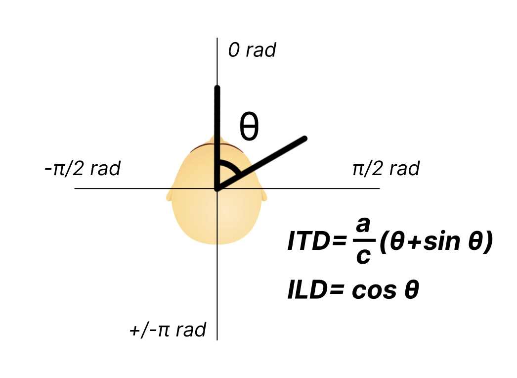
For simplicity, we used the same calculations for ITD and ILD as in the 2021 and 2015 projects (linked in References). In the formula, a is the head radius and c is the speed of sound. As shown in Figure 5, we chose 5 directions: θ=-π/3 -π/4, 0, π/3, and π/4 radians. For each of the directions, we calculate the ITD and ILD and use the results to manipulate the corresponding input audio. Additionally, ITD was also multiplied by 40,000 cycles per second (time between each ISR call) to represent delays in cycles. This was because the spatial audio algorithm was all done in the ISR for each core. For all 5 directions, ITD and ILD were calculated by hand so that the Pico did not need to do any calculations. The results for all 5 directions are listed below:
Direction #0 and #4: ITD = 20; ILD = 0.5
Direction #1 and #3: ITD = 16; ILD = 0.7
Direction #2: ITD = 0; ILD = 1
Note that these results were also slightly adjusted based on user experience. Say if direction 1 were chosen, then the audio to the right ear (governed by core 1) would remain unchanged in time and amplitude and the audio to the left ear would be delayed by ITD and its amplitude would be decreased by ILD. For a better user experience in the game we made both audios quieter by dividing the audio by a small number to decrease the voltage.
Hardware/Software Tradeoffs
Because we wanted spatial audio to be present in both ears, the two input audios needed to be summed together and output into the DAC in both interrupt service routines. The Pico’s processing speed could not slow down as both cores needed to do spatial audio algorithms on their respective input audio and send it to both ears at the same time. This meant that we needed to be careful about how the audio is inputted. We discussed the idea of using a microphone to pick up the audio as input, but that would require additional hardware, a high enough sampling frequency, and additional audio sampling and calculations in the software, potentially slowing the Pico’s processing speed. We also discussed downloading audio and putting it on the Pico. But because the Pico has a small RAM and our game audio is 5 minutes long, this idea was not applicable. Thus, we decided to use two additional audio jacks to input the game audio. This way the Pico could directly read the audio input, does not need to store the entire audio in memory, and does not need to sample the audio. The pico would be able to apply spatial audio algorithms directly on the data it reads from the ADC input.
Copyrights
There are no existing patent, copyright, and/or trademark infringements to the best of our knowledge.
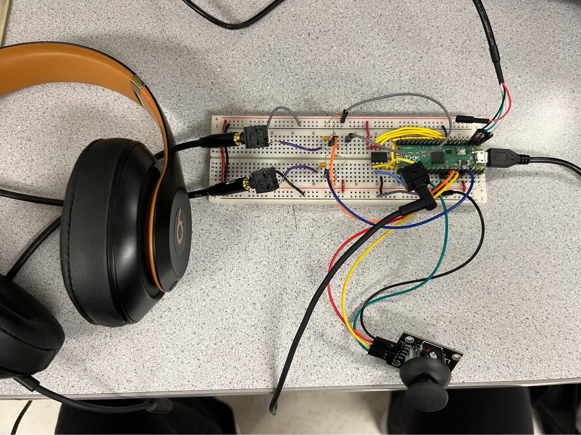
Hardware Design
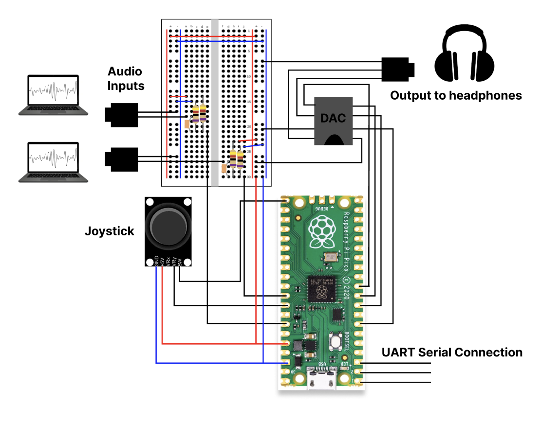
The main hardware components are the RP2040 Microcontroller, Raspberry Pi Pico, HW-504 Joystick, MCP4822 Digital-To-Analog Converter (DAC), 3.5 mm Audio Socket (x3), and headphones/speaker output. We also wrote and pre-recorded the audio files for the maze game. We separated the characters into two audio files, which were saved on two laptops as the two audio inputs. The characters that “approached” from the left and should therefore be left spatialized were saved on one laptop, while the characters that “approached” from the right and should be right spatialized were saved on the other laptop (Right: Liz, Clara, Sydney; Left: Ethan, Francis, Mr. Hopper). Both inputs ultimately reach each of the ears in the output headphones (see software section).
The Raspberry Pi Pico is mounted with the RP2040 microcontroller, which has a 2MB Flash and 40MHz clock frequency. Because the microcontroller has dual M0 + processor cores, we were able to use one core for each of the physical headphone channels (core 0 output to the right ear, core 1 output to the left ear). The RP2040 was also in charge of communicating with the two audio inputs, outputting the spatialized audio to the DAC, and accepting user input from the joystick.
The HW-504 Joystick is our user interface, where the player is able to move the joystick left or right in order to select the voice that they want to listen closer to. The joystick requires the ADC channel of the Pico in order to communicate with the RP2040. However, the two audio inputs also require the ADC pins and there are only 3 ADC pins on the Pico. Therefore, we used only the VRy connection to the joystick, which reads data only in one direction. Because we are holding the joystick sideways (connections are at the bottom), the VRy connection (instead of VRx) on the joystick actually reads data when the user moves the joystick left and right. One direction of data movement is enough for the purpose of telling whether the user has chosen left or right for the murder mystery.
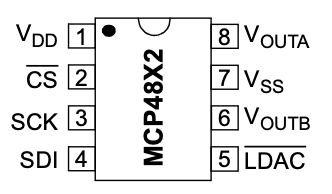
The MCP4822 DAC is a Digital-To-Analog Converter which takes digital input from the Pico and outputs an analog signal to the headphone jack. The DAC receives the digital signals of the spatialized audio (from core 0 and 1) from the SPI channel of the RP2040 microcontroller. It then converts the audio into two analog waveform outputs, using two channels, one outputted through the VOUTA pin and the other through the VOUTB pin. VOUTA and VOUTB then each connect to the data lines of the headphone audio socket, one for the left ear channel and the other for the right ear channel.
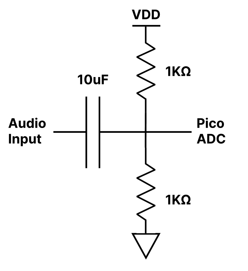
The audio inputs and headphone output were wired using 3.5 mm audio sockets and audio jack cords. Because the analog audio inputs range between +/-1V and the Pico’s ADC inputs only read voltages between 0 and 3.3V, we used a simple voltage level shifter circuit using a voltage divider and capacitor. The capacitor and resistor values shown in the diagram below were calculated so that the ADC values stay between approximately 0.75V and 2.75V.
For the audio input sockets, the input recordings were not spatialized (left and right channels are the same) so we wired only one of each socket’s two data lines to the level shifter circuit.
One issue that we ran into was that certain headphones did not work properly with our audio output and would also interfere with our oscilloscope readings when plugged in. Regular earbuds either did not work at all or the sound was very quiet. On the other hand, we discovered that the speakers worked, and thankfully, a pair of Beats over-the-ear headphones worked as well, which we used for the final demo.
Software Design
The software involved in this project involves both of the cores on the RP2040 to spatialize the two audio input recordings from our laptops and output the left/right layered voices to the user’s headphones. The majority of the computation was calculated using timer interrupt service routines called on core 0 and core 1. Each core’s ISR is responsible for a different headphone channel, with the right ear output being in the ISR on core 0 and the left ear output being in the ISR on core 1. It is important to note that both input voices need to be heard on each ear of the headphones, just with different relative amplitudes and delays. Both ISRs update a history array, calculate the ILD/ITD values for the two input voices based on the direction that the user decides and write to the SPI channel for output to the DAC. Meanwhile, the user input from the joystick was taken care of in a separate protothread on core 0. This joystick thread reads the ADC input connected to the joystick and sets the global variables for the proper direction that each voice should be (see the “Game Design” section).
Timer ISRs
The interrupt service routines on cores 0 and 1 have very similar logic, with three main responsibilities: update the history array, set the ILD and ITD variables, and take the proper audio sample from each of the input recordings to output to the SPI channel.
We will discuss our method of adding delays to the audio using an example. If the maid Liz is standing on the right at direction #1 and the son Ethan is standing on the left at direction #3, we need to layer a louder Ethan and quieter Liz (with a delay) to output to the left ear (core 1). In contrast, we need to output a louder Liz and quieter Ethan (with a delay) to the right ear (core 0). The history array helps us keep track of the last 20 audio input samples of Liz and Ethan’s voice because we know from the maximum ITD (positions #0 and #4) is 20 cycles of delay. When we need Liz to be in direction #1 (45 degrees right), core 0 (right ear) will output the most recent audio sample (no delay) from the recording of Liz’s voice, while core 1 (left ear) will output an audio sample that is 16 samples (ITD) back by indexing into the history array. A similar logic will occur for Ethan, except he has a separate history array.
Because Liz and Ethan are on two different audio inputs, the ISR on core 0 constantly updates history_r (in this case, it’s Liz’s voice), while the ISR on core 1 updates history_l (in this case it’s Ethan’s voice). In order to update the respective history arrays, we first select the ADC input that connects to the laptop with Liz or Ethan’s recording. Then, using a for loop, we move all the items in the history array back by 1 and we save the newest ADC read to index 0 of the history array. This way, the current read is at index 0 and a value that is ITD samples back can be indexed by the ITD variable.
Next, in the ISR functions, the ILD and ITD variables are updated. In core 0, we use direction_r0 and direction_l0, which keep track of Liz and Ethan’s directions (#0-4) respectively. On core 1, we have a similar variable direction_r1 and direction_l1. Direction_r0 and direction_r1 always have identical values to each other while direction_l0 and direction_l1 are also always identical. The reason we separated the values for the two cores was because a previous version of our code used to “ping pong” between the left and right directions by setting the variable to a new value in each core. More about this version will be discussed later below.
We also use a variable called old_direction for each of the corresponding direction variables. In order to set the ILD and ITD for Liz, we check if direction_r has changed from old_direction_r, and if it has, we set the new ILD_r and ITD_r for Liz’s phase and amplitude shift. The same thing is done for Ethan by checking if direction_l has changed from old_direction_l and if so, setting ILD_l and ITD_l.
Finally, the ISRs must layer and output the spatialized voices to the SPI channel. In order to do this, we use a series of if statements to check direction_r and direction_l (i.e. Liz and Ethan’s positions). If we are on core 0 (right ear) and the direction is #3 or #4 (left side), this means that we need to add a delay and scale by ILD, so index into the history array and multiply the sample at index ITD by ILD. Similarly, on core 1 (left ear), if the direction is #0 or #1 (right side), we need to add a delay and scale by ILD. For the remaining directions, we choose the most recent audio sample (history[0]) without using ITD or ILD. We do this once for Liz and once for Ethan, which leaves us with the audio outputs for Liz and Ethan on each core. Because we have two voices instead of one, we have to scale down each so that they do not exceed the 3.3V output. Therefore, the output from directions #1,2,3 are divided by 2, and the outputs from directions #0 and #4 are divided by 10 so that the background voice can be even fainter for dramatic effect.
In order to output to the DAC, we add the chosen output samples from Liz and Ethan together and mask with the proper DAC_config_chan_A or DAC_config_chan_B. These are written to the SPI channel, which sends the audio to the DAC and then to the left and right channels of the headphones for the user to enjoy.
Joystick Thread
The joystick protothread is responsible for recording the user input from the joystick. Here, we first select the ADC input corresponding to the joystick and store that value as a variable. Next, we determine if that raw ADC value is either less than 1000, which means that the joystick has moved to the left, or if the value is greater than 3000, which means that the joystick has moved to the right. An important feature we added was an array of length 4, which is called joystick[4], which keeps track of the last 4 values of the joystick ADC read. If the last 4 reads were all the same direction, then we know that it is safe to set the global direction variables (see figure 3). If the user moves the joystick to the right, then the right voice moves to direction #2 and the left voice moves to direction #4. If the user moves the joystick to the left, then the left voice moves to direction #2 and the right voice moves to direction #0.
The reason that we added the joystick array was because we noticed that the joystick was outputting inconsistent data, where it would change direction for one cycle and then change back. The simple joystick array was able to fix this issue and provide a much smoother user experience.
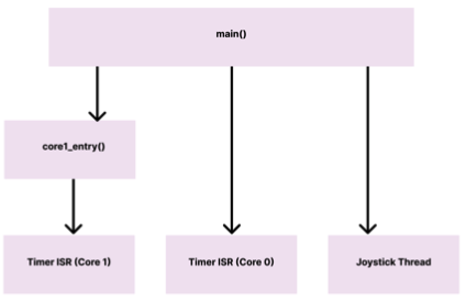
Main/core1 entry
The last component of our software is the main and core1_entry() functions, which are responsible for initializing the threads and ISRs on each core. The main function first initializes stdio/uart (which allows us to use printf statements) and also sets up all of our SPI pins for communication with the DAC. Next, we initialize the ADC pins for communication with the joystick and two audio inputs, and we also initialize the intercore semaphores between cores 0 and 1. Finally, we launch core1_entry, start the timer for 40kHz for the ISR on core 0, and add the joystick protothread. In the core1_entry function, we also start a timer for 40kHz for the ISR on core 1. With everything set up, the software can now run our murder mystery.
Features that didn’t make it to final demo
We used an iterative process to design the hardware and software of this spatial audio project. Therefore, a lot of the logic that we implemented to start that didn’t work or just didn’t make it to the final demo. One of the more time consuming features that we implemented was spatial audio using beeps instead of voice audio. Here, we will briefly describe some of the software that was involved in spatializing a series of beeps, which could “ping pong” between the left and right ears as well as move around your head with the joystick input.
In this version of our spatial audio, we generated audio beeps using the same Direct Digital Synthesis (DDS) algorithm that we used in lab 1 (cricket chirps). Each beep also included a ramp-up and ramp-down period with a rest between beeps. Below is the finite state machine that we used to create the time delays for the left and right ears. Our logic was based on the FSM that we had built in lab 1 for the crickets.
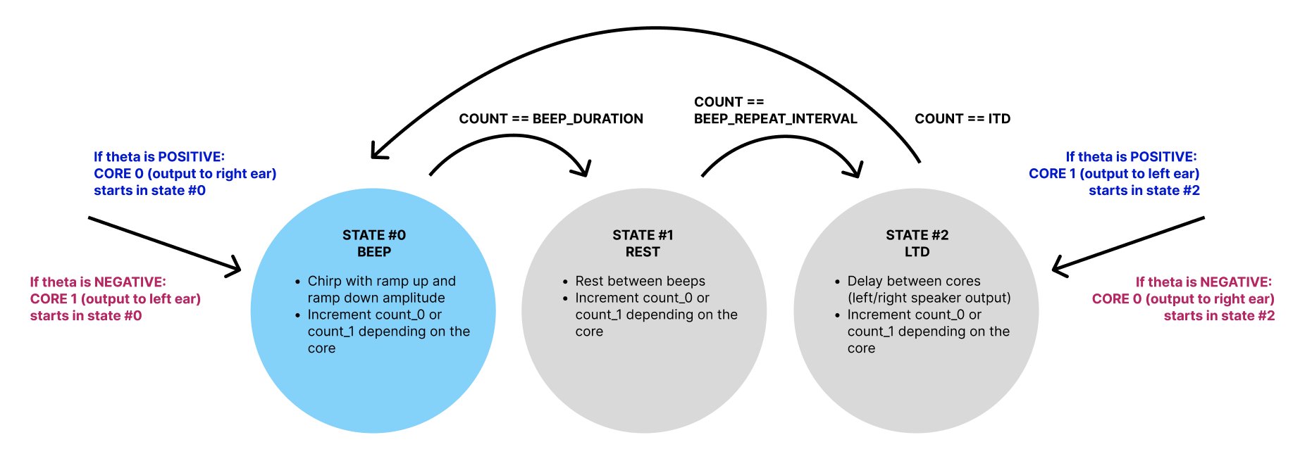
The FSM includes 3 states: one for the beep, one for the rest, and one for the LTD (time delay). We will go through an example of a beep that we want to come from the right side of the head (theta is positive). In this case, we want core 0 (right ear) to start in state #0 with a regular beep. Meanwhile, core 1 (left ear) starts in state #2 with the LTD. Both cores are using a counter and checking whether they have reached BEEP_DURATION, BEEP_REPEAT_INTERVAL, or ITD depending on their state, which allows them to change states. When core 1’s counter has counted up to ITD, it will move to the beep in state #0, except with an amplitude that is scaled by ILD.
If we want to create the ping pong effect where the beep bounces between the left and right ears, then core 0 must go to state #0, #1, and then #2 to LTD to allow core 1 to catch up. Meanwhile, core 1 did state #2, #0, and then #1. Here is when the two cores must now switch places so that the beep can transfer to the other side. We, therefore, flip theta to negative and follow the pink text in the diagram above (core 1 moves to state #0, and core 0 moves to state #2).
If we want to connect the joystick input and allow the user to pick which direction the beep comes from, then we only need to go into the LTD state once for the trailing core. Whenever we sense user input and the direction has changed, then the cores need to reset their states so that the proper delay is applied to the proper ear. With this version, we used both x and y directions for the joystick (2 ADC inputs), so we were able to utilize more directions. This however didn’t work in the final demo because as mentioned before, we only have 3 ADC pins on the Pico and the two voice recording inputs for the demo required two of those ADC pins.
Results
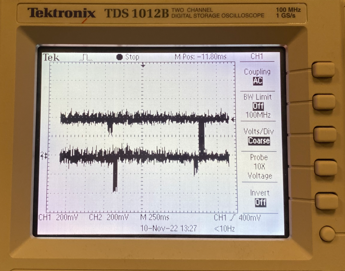
As mentioned before, the first step was to generate and test spatial audio with synthesized beeps. The beeps were generated with direct digital synthesis based on the chirp generated in a previous lab. We first tested the utilization of two cores with the chirps generated with direct digital synthesis as shown below in Figure 11.
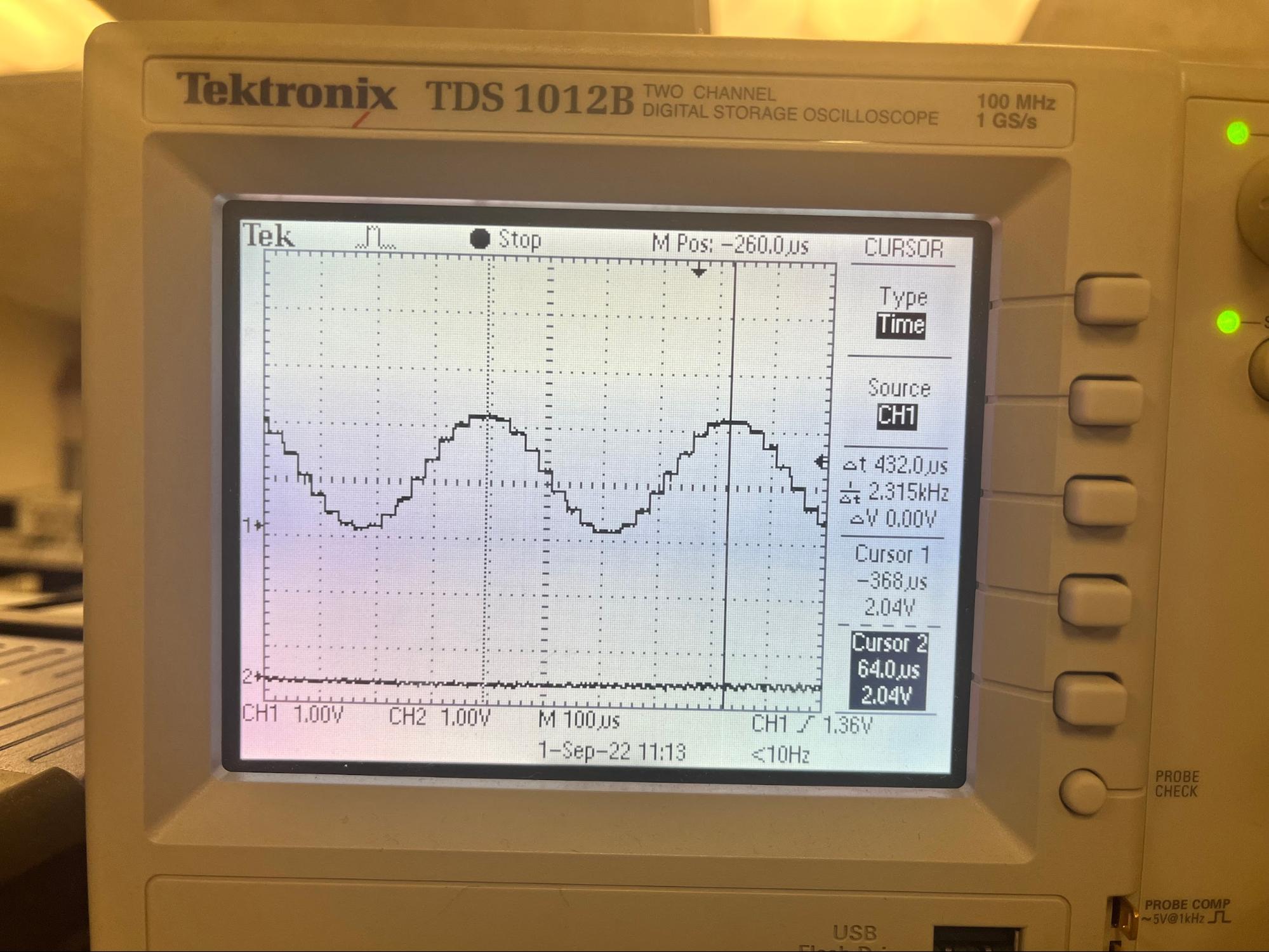
This allowed us to check not only the audio output working but also the concurrency of both cores. After the test, we simplified the sound to beep and implemented two beeps into both cores. Each beep was generated with a calculated amount of time and amplitude difference for a specific direction. The calculated delay and amplitude difference were first tested with 45 degrees left and checked with both a speaker and oscilloscope as shown in the Figure 12.
The oscilloscope showed a clear delay applied to the sound; however, it was a bit unclear with the ears. The difference in amplitude was modified to make the spacial audio more distinct but also not too loud in the ears. It was important to find the ideal range of amplitude using a headphone as an output because the project expects the user to use a headphone or earbuds. This test ensures the performance of the spatial audio and the safety of the ears. With the same process, the directions from the front and right 45, 90 degrees and left 45, 90 degrees were tested and successfully implemented with modifications.
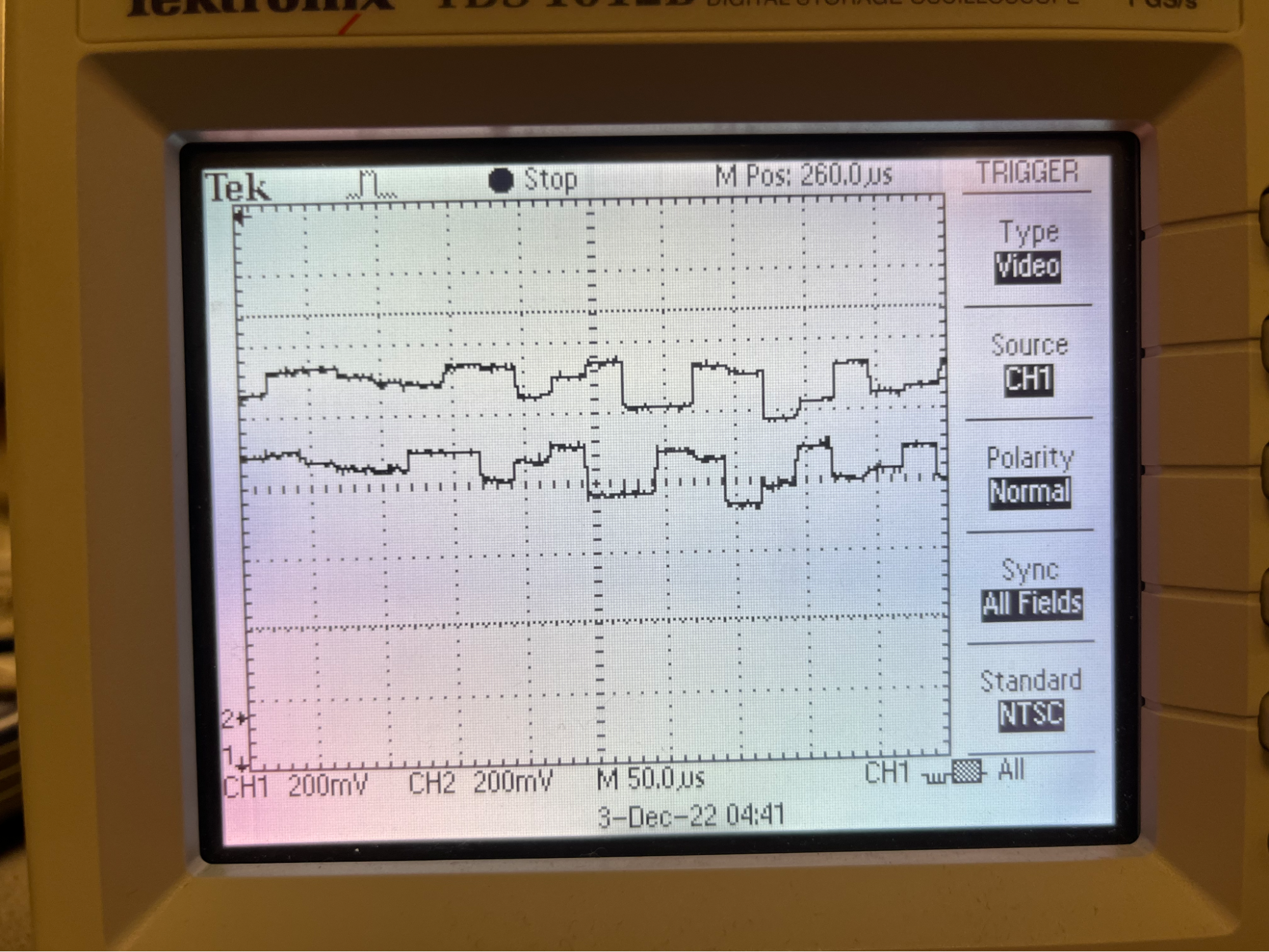
After successfully testing with beeps, we implemented two audio jacks into our circuit and used music from the laptop to test spatial audio with different sounds. The same music was inputted into two audio jacks, and each input audio was modified based on the algorithm in a core. With different music, the audio was clear with a direction applied, and the delay was successfully made in both as shown in Figure 13.
Finally, the recorded audio was inputted and tested. The audio test result can be heard in the demo video below.
For the user input, the joystick was implemented and first tested on PuTTY. We tested the output direction of the joystick by using serial output that reads the raw data in x and y. The joystick was successfully implemented as we could check the output numbers in both directions. However, we realized the speed of the serial input was too fast. This is an unnecessary use of energy and computation time which leads to noisy audio output, so we decided to make the yield time 40,000 microseconds. We then applied the joystick to control the direction of the music and checked that the input control works in all directions. To increase usability and simplicity, we stored the last direction of the joystick so that the user does not have to keep holding the joystick in a specific direction to keep the state.
Conclusion
The project successfully implements a spatial audio feature into the interactive murder mystery game with a joystick. During the implementation, we had several challenges in solving noise issues and a limit in the number of ADC inputs for Raspberry Pi Pico. In hardware, the circuit was simplified and replaced with larger capacitors to stabilize the signals. The audio output ports were reduced from three to one due to the noise that was created by the multiple output ports. In software, the code was optimized with less computation and input reads to minimize the noise in the audio output. The number of user input directions was also changed from the original plan. To take the inputs from all directions (360 degrees), four ADC ports are needed: two for audio ports and two for x and y inputs in the joystick. We used two input directions (left/right) for the project because RP2040 has three ADC input ports.
In the future, we would like to expand this game to a multi-user game that players can play and interact with each other in the game. This would require multiple RP2040s to interact and share the data concurrently. Also, we would like to implement a full-directional joystick input for spatial audio from all directions, as well as an extended logic flow for the game.
Demonstration Video
References
Spatial AudioSpatial Audio PPT
2021 project
2015 project
Pico UART transmission
DAC datasheet
Direct Digital Synthesis
Audio Jack
Joystick
Pico datasheet
Joystick example code
Pico SDK datasheet
Professor Hunter Adams ECE4760 Lab 1 Code
Appendix A: Permissions
The group approves this report for inclusion on the course website.
The group approves the video for inclusion on the course youtube channel.
Appendix B: Code
Check out our Code Repository :D The main file in which our code is written is called 'final.c'
https://github.com/Minjk121/ECE4760_Final
/*
Minjung Kwon, Ann Xu, Amy Wang
Spacial Audio Project

This project implements spatial audio into a fun and interactive murder mystery game.
We generated self-recorded audio and passed it to headphones while applying a spatial audio algorithm to the input audio.
To the headphone user, the audio appears to be coming from the specific direction the user chooses with the joystick.
The goal is to closely mimic how sounds in real life reach our ears, depending on where the sound is coming from.
 */

// Include necessary libraries
#include <stdio.h>
#include <math.h>
#include <string.h>
#include "pico/stdlib.h"
#include "pico/multicore.h"
#include "hardware/sync.h"
#include "hardware/spi.h"
#include "hardware/adc.h"

// Include protothreads
#include "pt_cornell_rp2040_v1.h"

// Macros for fixed-point arithmetic (faster than floating point)
typedef signed int fix15 ;
#define multfix15(a,b) ((fix15)((((signed long long)(a))*((signed long long)(b)))>>15))
#define float2fix15(a) ((fix15)((a)*32768.0))
#define fix2float15(a) ((float)(a)/32768.0)
#define absfix15(a) abs(a)
#define int2fix15(a) ((fix15)(a << 15))
#define fix2int15(a) ((int)(a >> 15))
#define char2fix15(a) (fix15)(((fix15)(a)) << 15)
#define divfix(a,b) (fix15)( (((signed long long)(a)) << 15) / (b))

// SPI data
uint16_t DAC_data_1 ; // output value
uint16_t DAC_data_0 ; // output value

// Audio History
float history_r[21] ;
float history_l[21] ;
float new_r ;
float new_l ;

// DAC parameters (see the DAC datasheet)
// A-channel, 1x, active
#define DAC_config_chan_A 0b0011000000000000
// B-channel, 1x, active
#define DAC_config_chan_B 0b1011000000000000

//SPI configurations (note these represent GPIO number, NOT pin number)
#define PIN_MISO 4
#define PIN_CS   5
#define PIN_SCK  6
#define PIN_MOSI 7
#define LDAC     8
#define LED      25
#define SPI_PORT spi0
#define CORE_0   2
#define CORE_1   3

// Semaphore
struct pt_sem core_1_go, core_0_go ;

// Constants
#define head_radius 9.0       // a
#define speed_sound 34000.0   // c

// Direction Variables
int direction_r0 = 1;
int direction_r1 = 1;
int direction_l0 = 3;
int direction_l1 = 3;

// Direction History Variables
volatile int old_direction_r0 = 10;
volatile int old_direction_r1 = 10;
volatile int old_direction_l0 = 10;
volatile int old_direction_l1 = 10;

// Algorithm Variables
float ILD_r;
int ITD_r;
float ILD_l;
int ITD_l;

// ADC Channel and pin
#define ADC_CHAN_0 0
#define ADC_CHAN_1 1
#define ADC_CHAN_2 2
#define ADC_PIN_28 28
#define ADC_PIN_26 26
#define ADC_PIN_27 27

// audio inputs
int adc_audio_r0;
int adc_audio_r1;
int adc_audio_l0;
int adc_audio_l1;

// Joystick Variables
int joystick[4];
int direction = 2;

//========================================================================
// Timer ISR on Core 1 - LEFT
//========================================================================
// Applies algorithm variables based on the joystick input direction.

bool repeating_timer_callback_core_1(struct repeating_timer *t) {

    // ADC input for left audio
    adc_select_input(0);

    // Update history data
    new_l = adc_read();
    for (int i =1; i<=20; i++) {
        history_l[i] = history_l[i-1];
    }
    history_l[0] = new_l;

    // Update ILD and ITD based on input data (right)
    if (direction_r1 != old_direction_r1) {
        if (direction_r1==0 || direction_r1==4){
            ILD_r = 0.5 ; // 80 degrees
            ITD_r = 20 ; // 80 degrees
        }
        else if (direction_r1==1 || direction_r1==3){
            ILD_r = 0.7 ; // 45 degrees
            ITD_r = 16 ; // 45 degrees
        }
        else if (direction_r1==2){
            ILD_r = 1 ; // 0 degrees
            ITD_r = 0 ; // 0 degrees
        }
        old_direction_r1 = direction_r1;
    }

    // Update ILD and ITD based on input data (left)
    if (direction_l1 != old_direction_l1) {
        if (direction_l1==0 || direction_l1==4){
            ILD_l = 0.5 ; // 80 degrees
            ITD_l = 20 ; // 80 degrees
        }
        else if (direction_l1==1 || direction_l1==3){
            ILD_l = 0.7 ; // 45 degrees
            ITD_l = 16 ; // 45 degrees
        }
        else if (direction_l1==2){
            ILD_l = 1 ; // 0 degrees
            ITD_l = 0 ; // 0 degrees
        }
        old_direction_l1 = direction_l1;
    }

   // Update amplitude in audio (right)
    if (direction_r1==1) {
        adc_audio_r1 = (int) (history_r[ITD_r]*ILD_r)/2;
    }
    else if (direction_r1==0) {
        adc_audio_r1 = (int) (history_r[ITD_r]*ILD_r)/10;
    }
    else if (direction_r1==4) {
        adc_audio_r1 = (int) (history_r[0])/10;
    }
    else { // direction 1,2
        adc_audio_r1 = (int) (history_r[0])/2;
    }

    // Update amplitude in audio (left)
    if (direction_l1==1) {
        adc_audio_l1 = (int) (history_l[ITD_l]*ILD_l)/2;
    }
    else if (direction_l1==0) {
        adc_audio_l1 = (int) (history_l[ITD_l]*ILD_l)/10;
    }
    else if (direction_l1==4){
        adc_audio_l1 = (int) (history_l[0])/10;
    }
    else {
        adc_audio_l1 = (int) (history_l[0])/2;
    }

    // Update 12-bit DAC with last 12 bits in ADC
    DAC_data_1 = (DAC_config_chan_A | ((adc_audio_r1 + adc_audio_l1) & 0xfff))  ;
    spi_write16_blocking(SPI_PORT, &DAC_data_1, 1) ;

    return true;

}

//========================================================================
// Timer ISR on Core 0 - RIGHT
//========================================================================
// Applies algorithm variables based on the joystick input direction.

bool repeating_timer_callback_core_0(struct repeating_timer *t) {

    // ADC input for right audio
    adc_select_input(2);

    // Update history data
    new_r = adc_read();
    for (int i =1; i<=20; i++) {
        history_r[i] = history_r[i-1];
    }
    history_r[0] = new_r;

    // Update ILD and ITD based on input data (right)
    if (direction_r0 != old_direction_r0) {
        if (direction_r0==0 || direction_r0==4){
            ILD_r = 0.5 ; // 80 degrees
            ITD_r = 20 ; // 80 degrees
        }
        else if (direction_r0==1 || direction_r0==3){
            ILD_r = 0.7 ; // 45 degrees
            ITD_r = 16 ; // 45 degrees
        }
        else if (direction_r0==2){
            ILD_r = 1 ; // 0 degrees
            ITD_r = 0 ; // 0 degrees
        }
        old_direction_r0 = direction_r0;
    }

    // Update ILD and ITD based on input data (left)
    if (direction_l0 != old_direction_l0) {
        if (direction_l0==0 || direction_l0==4){
            ILD_l = 0.5 ; // 80 degrees
            ITD_l = 20 ; // 80 degrees
        }
        else if (direction_l0==1 || direction_l0==3){
            ILD_l = 0.7 ; // 45 degrees
            ITD_l = 16 ; // 45 degrees
        }
        else if (direction_l0==2){
            ILD_l = 1 ; // 0 degrees
            ITD_l = 0 ; // 0 degrees
        }
        old_direction_l0 = direction_l0;
    }

    // Update amplitude in audio (right)
    if (direction_r0==3){
        adc_audio_r0 = (int) (history_r[ITD_r]*ILD_r)/2;
    }
    else if (direction_r0==4){
        adc_audio_r0 = (int) (history_r[ITD_r]*ILD_r)/10;
    }
    else if (direction_r0==0){
        adc_audio_r0 = (int) (history_r[0]/10);
    }
    else {
        adc_audio_r0 = (int) (history_r[0]/2);
    }

    // Update amplitude in audio (left)
    if (direction_l0==3) {
        adc_audio_l0 = (int) (history_l[ITD_l]*ILD_l)/2;
    }
    else if (direction_l0==4) {
        adc_audio_l0 = (int) (history_l[ITD_l]*ILD_l)/10;
    }
    else if (direction_l0==0){
        adc_audio_l0 = (int) (history_l[0])/10;
    }
    else { // direction 1,2
        adc_audio_l0 = (int) (history_l[0])/2;
    }

    // Update 12-bit DAC with last 12 bits in ADC
    DAC_data_0 = (DAC_config_chan_B | ( adc_audio_r0 + adc_audio_l0 & 0xfff))  ;
    spi_write16_blocking(SPI_PORT, &DAC_data_0, 1) ;

    return true;

}

//========================================================================
// PT_Thread_Joystick
//========================================================================
// Joystick user input to ADC

static PT_THREAD (protothread_joystick(struct pt *pt))
{
    PT_BEGIN(pt) ;

    while(1) {
        PT_YIELD_usec(40000); // 40000 microseconds
        adc_select_input(1);
        uint adc_x_raw = adc_read();

        // Updates direction based on the raw data
        if(adc_x_raw < 1000) {
            direction=4;
        }
        else if (adc_x_raw > 3000) {
            direction=0;
        }

        for (int i =1; i<4; i++) {
            joystick[i] = joystick[i-1];
        }

        joystick[0] = direction;
        if (joystick[0]==joystick[1] && joystick[1]==joystick[2] && joystick[2]==joystick[3]) {
            if (direction==0 || direction==1) {
                direction_r0 = 2;
                direction_r1 = 2;
                direction_l0 = 4;
                direction_l1 = 4;
            }
            else if (direction==3 || direction==4) {
                direction_r0 = 0;
                direction_r1 = 0;
                direction_l0 = 2;
                direction_l1 = 2;
            }
        }

    }
    PT_END(pt) ;
}

//========================================================================
// Core 1 Entry Point - Left Ear
//========================================================================

void core1_entry() {
    // Create an alarm pool on core 1
    alarm_pool_t *core1pool ;
    core1pool = alarm_pool_create(2, 16) ;

    // Create a repeating timer that calls repeating_timer_callback.
    struct repeating_timer timer_core_1;

    // Negative delay so means we will call repeating_timer_callback, and call it
    // again 25us (40kHz) later regardless of how long the callback took to execute
    alarm_pool_add_repeating_timer_us(core1pool, -25,
        repeating_timer_callback_core_1, NULL, &timer_core_1);

    // Start scheduler on core 1
    pt_schedule_start ;

}


//========================================================================
// Core 0 Entry Point - Right Ear
//========================================================================
int main() {
    // Initialize stdio/uart (printf won't work unless you do this!)
    stdio_init_all();
    printf("Hello, friends!\n");

    // Initialize SPI channel (channel, baud rate set to 20MHz)
    spi_init(SPI_PORT, 20000000) ;
    // Format (channel, data bits per transfer, polarity, phase, order)
    spi_set_format(SPI_PORT, 16, 0, 0, 0);

    // Map SPI signals to GPIO ports
    gpio_set_function(PIN_MISO, GPIO_FUNC_SPI);
    gpio_set_function(PIN_SCK, GPIO_FUNC_SPI);
    gpio_set_function(PIN_MOSI, GPIO_FUNC_SPI);
    gpio_set_function(PIN_CS, GPIO_FUNC_SPI) ;
    gpio_set_function(CORE_0, GPIO_FUNC_SPI);
    gpio_set_function(CORE_1, GPIO_FUNC_SPI) ;

    // Map LDAC pin to GPIO port, hold it low (could alternatively tie to GND)
    gpio_init(LDAC) ;
    gpio_set_dir(LDAC, GPIO_OUT) ;
    gpio_put(LDAC, 0) ;

    // Map LED to GPIO port, make it low
    gpio_init(LED) ;
    gpio_set_dir(LED, GPIO_OUT) ;
    gpio_put(LED, 0) ;

    // Intialize Cores
    gpio_init(CORE_0) ;
    gpio_init(CORE_1) ;

    // ADC INIT FOR JOYSTICK
    stdio_init_all();
    adc_init();

    // Make sure GPIO is high-impedance, no pullups etc
    adc_gpio_init(26);
    adc_gpio_init(27);
    adc_gpio_init(28);

    // Initialize the intercore semaphores
    PT_SEM_SAFE_INIT(&core_0_go, 1) ;
    PT_SEM_SAFE_INIT(&core_1_go, 0) ;

    // Launch core 1
    multicore_launch_core1(core1_entry);

    struct repeating_timer timer_core_0;

    // Negative delay so means we will call repeating_timer_callback, and call it
    // again 25us (40kHz) later regardless of how long the callback took to execute

    add_repeating_timer_us(-25,
        repeating_timer_callback_core_0, NULL, &timer_core_0);

    // add joystick interface
    pt_add_thread(protothread_joystick) ;

    // Start scheduling core 0 threads
    pt_schedule_start ;

}
Appendix C: Parts List
- Raspberry Pi Pico $5.00 - Provided in lab
- Audio Jack x3 $3.03 - Provided in lab
- Joystick $5.00 - Provided in lab
- DAC $3.77 - Provided in lab
- Beats Headphones - Already owned by Amy
- Capcitors, Resistors, Breadboard, and Wires - Provided in lab
Total: $16.80
Note that any parts purchased but not used in the final demonstration are not inlcuded in the parts list. For example, we asked Hunter to buy a 3-Way Stereo Splitter Audio Cable but did not end up using it, thus it is not included in the parts list.
Appendix D: Work Distribution
Minjung Kwon
mk2592@cornell.eduBuilt input audio jack circuits
Worked with Amy and Ann to code and debug the Pico to do spatial audio algorithms on the input audio
Amy Wang
yw575@cornell.eduBuilt DAC circuit and output audio circuit
Worked with Minjung and Ann to code and debug the Pico to do spatial audio algorithms on the input audio
Ann Xu
asx3@cornell.edu
asx3@cornell.eduCreated game scirpt and recorded the audio for the game
Worked with Minjung and Amy to code and debug the Pico to do spatial audio algorithms on the input audio
Appendix E: Game Solution
**SPOILER ALERT**
So who actually poisoned Mrs. Hopper you may ask?
Well it was a combination of several people in the house. If you remember from scene 1, Mrs. Hopper and her son Ethan had tea in the morning and Mrs. Hopper LOVES HONEY. In fact she got a new shipment of honey that the maid Liz fetched from the drawing room table.
In scene 2, the daughter Clara was painting in the drawing room and the gardener Francis was oiling the door, also in the drawing room. Depending on which version you heard, one of these two left their paint glaze / lithium oil in a small bottle on the drawing room table that morning.
In scene 3, Mr. Hopper asks the cook Sydney to clean up all the bottles from the drawing room table from the new shipment of honey, jams, and vinaigrettes. If you heard Sydney, she mentions the random bottle of what she thought was honey that someone left on the table that she put away in the cabinet. Turns out, it probably wasn’t honey…
We knew you could solve it, thanks for your help!