Final Project Report
Brian Hsu (hh543), Mariko McMurtry (mkm249), Yinjie Zhao (yz483)
We designed a proof of concept plate recognition system that automatically recognizes and release cars from the parking lot.
Machine learning algorithms are becoming more prevalent in the automatization of various human tasks. Machine interpreting handwritten information has a myriad of applications such as post mail sorting, bank check processing, form data entry, etc. Mundane tasks that take humans excessive time and are prone to errors can be accurately and quickly resolved by machines with little to no mistake. Our inspiration for building a plate recognition system came from observing a fancy parking lot gating system at a mall in San Diego. The mall was in the heart of town with high foot and car traffic every day. The gates would automatically open up for the customers that are leaving if they had already paid. The infrastructure allowed for a smooth exiting of cars without the hassle of a gatekeeper sitting uncomfortably in a small booth, under the sun, slowing things down.
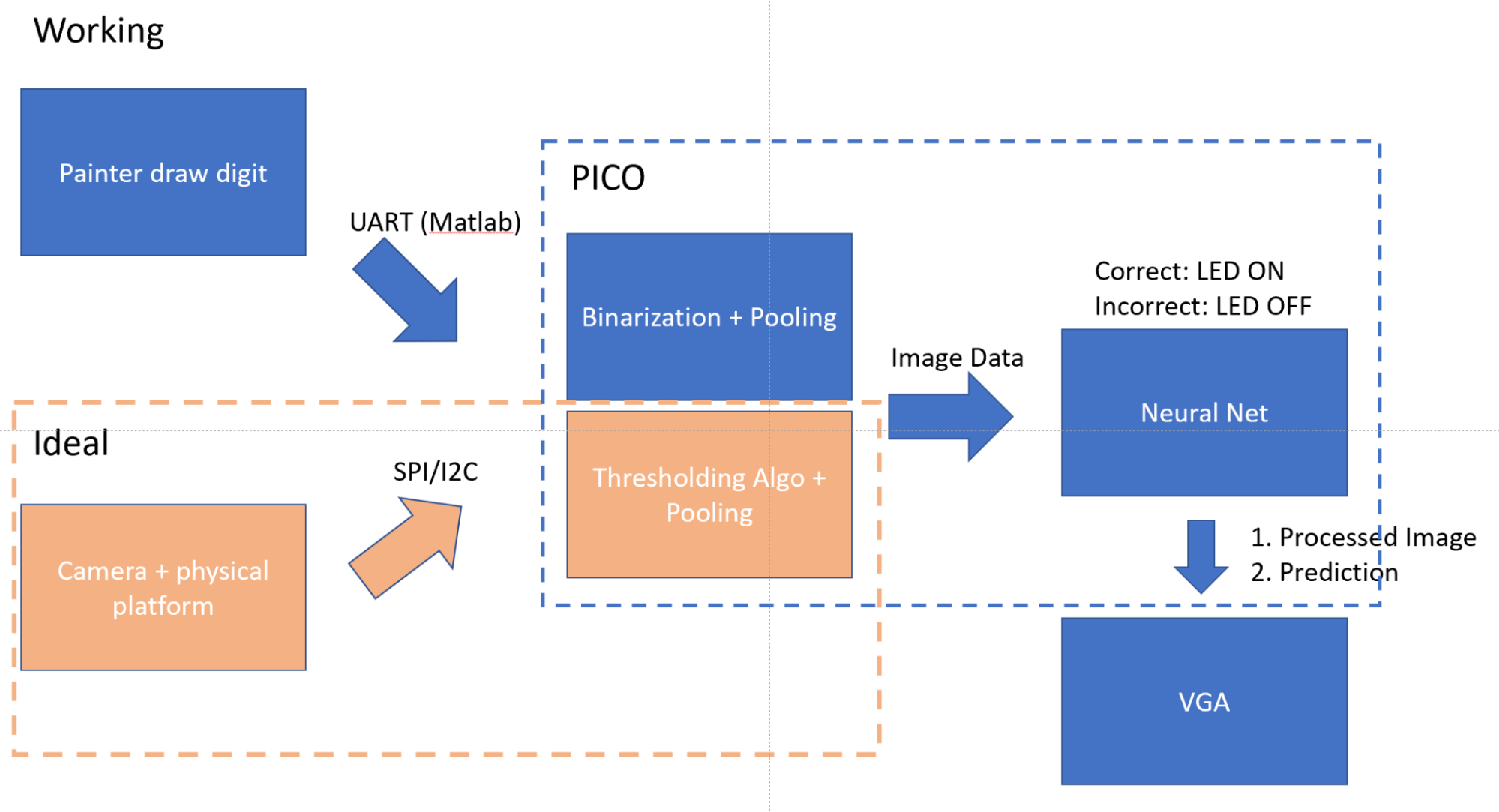
Without knowledge of the exact underlying technology, we made an educated guess that the system operated on a camera recognition system and decided to recreate it. We wanted to build a minimal viable system with a PICO running a machine learning algorithm that parses the camera information to perform digit recognition and sends the processed information and prediction to the VGA for display of results. Figure 1 is a diagram of the overall infrastructure, including the working version and ideal scenario.
Figure 1. System Infrastructure Diagram
The ideal approach implements a camera peripheral which is probed by the PICO to take a picture. The image data is transmitted via SPI or I2C to the PICO. We binarize the image data with a thresholding algorithm to combat external environmental variables such as lighting and pool the image to dimensions to fit our neural network model. The network is pre-trained with Matlab to recognize binarized 20 by 20 digit images. The input image and prediction is then drawn onto the VGA for display of results and a correct prediction will light up an LED that symbolizes the opening of a gate.
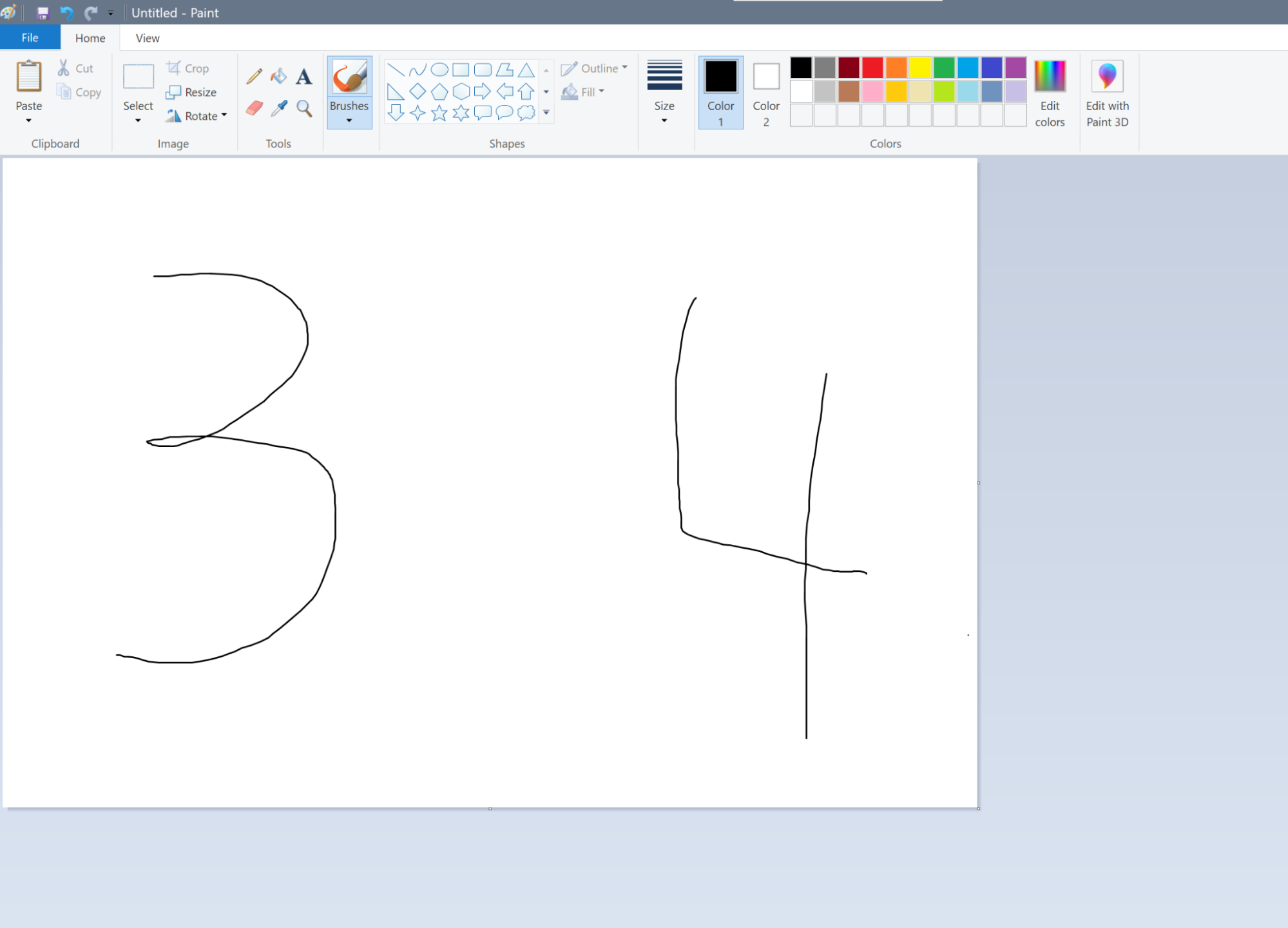
Unfortunately, we couldn’t get the camera to work so we pivoted to an alternative to showcase the potential results. Instead of feeding camera information to the PICO. We hooked up an UART channel that streams 256-color bitmaps created by the paint app to replace an actual person writing on a platform being captured by the camera. The thresholding algorithm is replaced with a more rudimentary cutoff algorithm since the input environment is more fixed.
We will still talk about our understanding and findings in getting the camera to work in the following sections.
Figure 2. Paint App
Mathematical Background
The main mathematical element to this project is the deep learning neural network algorithm that is implemented on the PICO. There are actually many algorithms that could be used for digit recognition from K-Nearest Neighbors to Multilayer Convolutional Neural Networks. KNN could potentially have low accuracy (low 90s if lucky) depending on the dataset used for training. On the other hand, complicated convolutional neural networks require too much memory (i.e. training dataset for KNN has the same problem) for the PICO to handle. We ended up settling with something in between, which is a multilayer perceptron model with 3 layers (i.e. input layer, hidden layer, output layer). This still pushed the PICO stack memory to its limits which will be discussed later.
Multilayer Perceptron Model
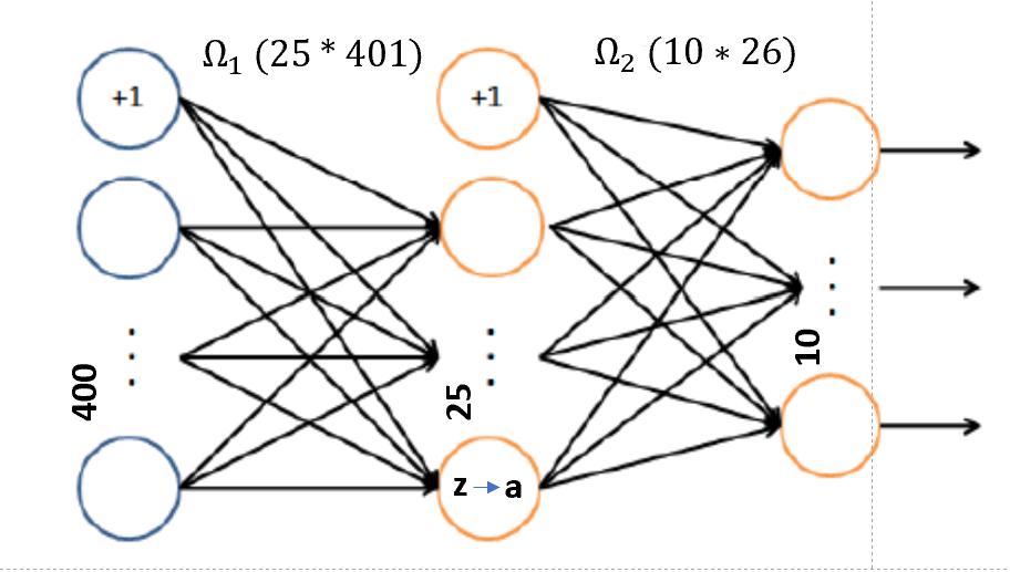
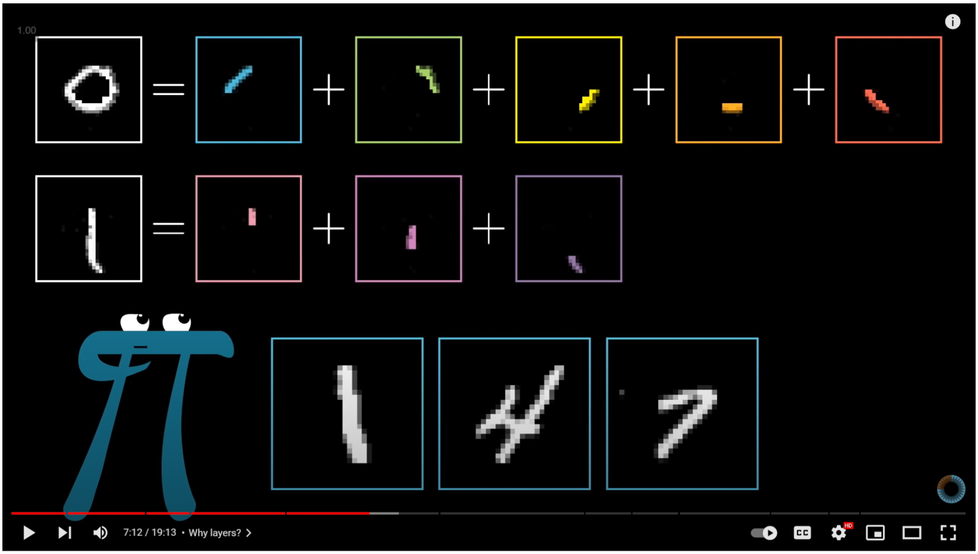
The layers of the network are 400 -> 25 -> 10 for the input layer, hidden layer and output layer, respectively. The input 400 is for a 20 by 20 image array, each value representing the value of a pixel (i.e. this is binarized). The middle layer values are the linear combination sum of the input values and the pre-trained weights. The linear combination value of each node is passed through an activation function to introduce non-linearity before going to the next layer. The activation function we chose for this model is the sigmoid function Figure 3 which is  . By passing the value through the sigmoid function, we are able to have a more definitive value for the influence of a perceptron. This helps with the prediction of the neural network. The last output layer has 10 perceptrons representing the 10 different digits (i.e. 0-9). The output perceptron that has the largest value is chosen as the prediction. It is easy to understand the meaning behind the input layer and the output layer, yet the hidden layer often lacks some intuitive explanation. Figure 4 is a snippet of deep learning video on Youtube from 3Blue1Brown that provides a reasonable visual insight behind the hidden layer. Essentially, the hidden layer selects pixels to form strokes that compose a digit. The pixels are the basic building block, and the hidden layer contains these intermediary blocks that form a digit.
Figure 3. Neural Network Model
Figure 4. Hidden Layer Intuition [# 3blue1brown reference]
Dataset & Training
Our dataset contains 5000 samples with 500 of each digit. The data originally came in some type of float representation so we made use of the thresholding algorithm to binarize the dataset. We used the dataset to train the weights via back propagation with Matlab. We will hold from discussing too in depth on the derivation of backpropagation. Essentially, backpropagation identifies which pathway (i.e. weights) in a neural network is more influential in the final prediction and updates all the weights to arrive at the desired prediction [8]. This is done by computing the partial derivative of the loss function with respect to all the weights.
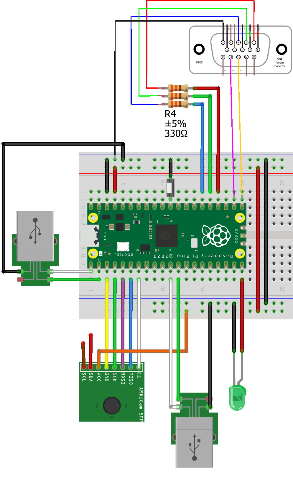
This lab involves three major parts in hardware, one is the OV2640 camera circuit (replaced with Matlab communication via UART), another one is the LED and the last one is the VGA. The below Figure illustrates the overall hardware connection between the RP2040, the VGA monitor, and the OV2640 camera. We were able to get the camera working but since it wasn’t used in the final infrastructure, we reconfigured the GPIO pins for I2C to UART.
Figure 5. Overall Setup
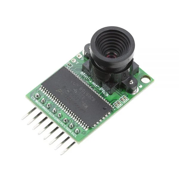
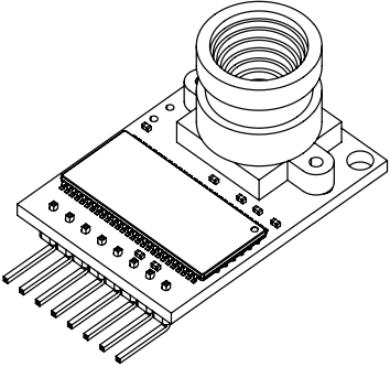
Our camera is equipped with a 2-megapixel CMOS OV2640 image sensor. It supports RAW, YUV, RGB, and JPEG format outputs; also supports UXGA, SVGA, VGA, QVGA, CIF, and QCIF resolutions.
Figure 6. Camera board
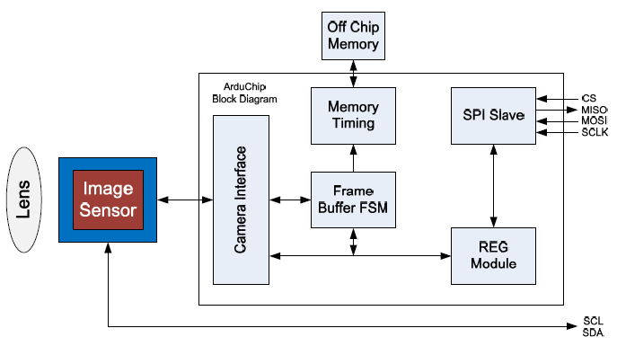
The camera contains two interfaces, I2C for the sensor configuration, SPI for camera commands and data stream, handles the complex memory and user interface hardware timing.
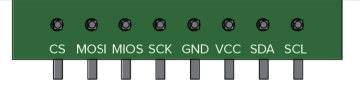
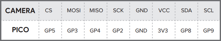
Figure 8 shows the camera board pinouts, unlike the Arduino, Pi Pico has limited GPIOs but we still found a way to make connections, as the figure 9 shows below.
Figure 8. Camera Module Pinouts
Figure 9. Pin Mapping
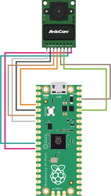
Then we following the table above to complete the connections, as the figure shows below.
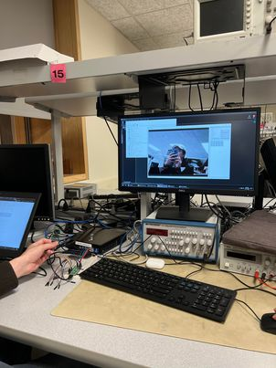
Figure 10. Connection with Pico
Figure 11. Camera Working
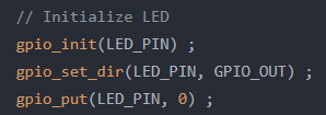
We hooked up an LED to GP15. The purpose of this is to use LED as an indicator, if the handwriting prediction is correct, then the LED will light up, no light otherwise. First we initialize the LED by set the GPIO #15 to output, and pull it to logic zero.
Figure 12. LED Initialization
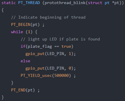
Then we have a thread called protothread_blink, which monitors the plate_flag, and set the GPIO to logic one if the flag is true.
Figure 13. LED thread
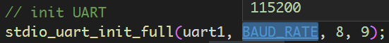
The Pi Pico have two UARTs, one we used (UART_0) for serial command input and output (GP0 and GP1), the other one (UART_1) is on GP8(TX) and GP9(RX), which we use it for upload bitmap image data. We initialize the UART_1 in the main function with the 115200 baud rate. During our test and debug, we found there is a consistency issue when deal with two UARTs. When we send data via the UART_1 and at the same time we read the UART_0, sometimes it works while sometimes it does not. We still cannot resolve this issue.
Figure 14. UART_1 setup
Paint App
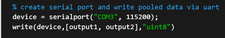
Matlab allows for an easy setup of UART connection by calling the serial port function and specifying the channel and baud rate (i.e. matching the PICO). Writing and reading can be carried out after the port is established.
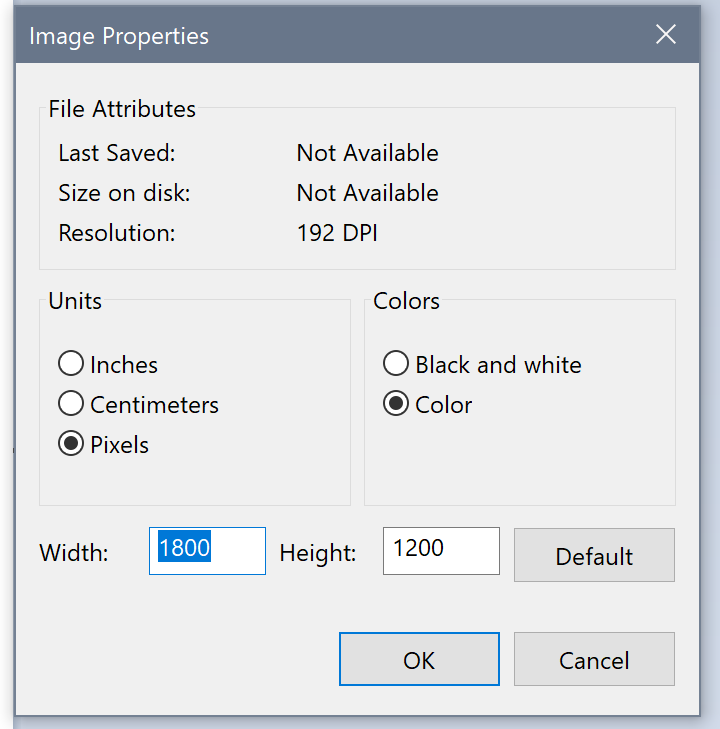
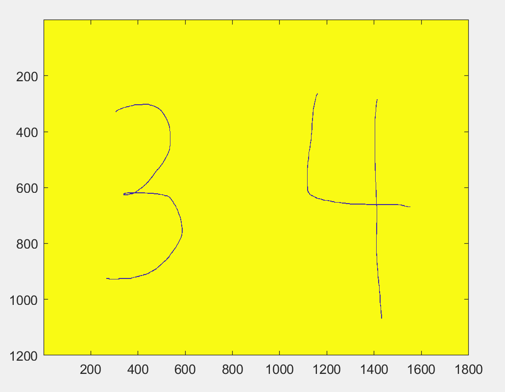
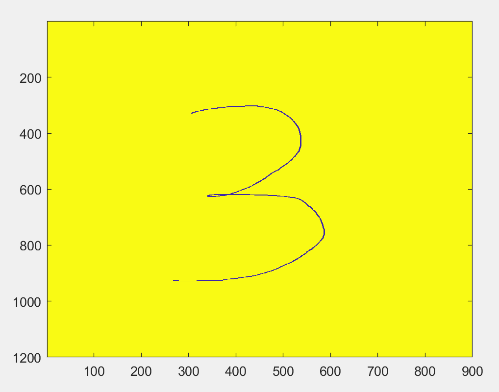
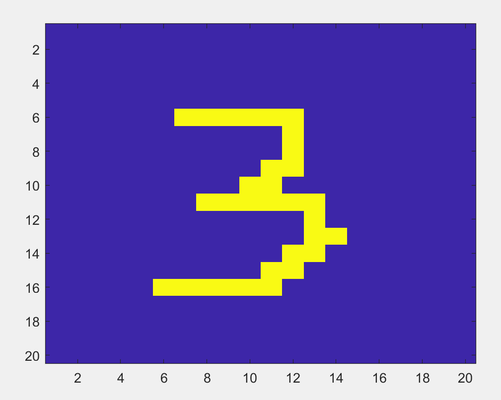
We specify the canvas dimensions via image properties on the paint application. In this case, our dimensions are 1800x1200 pixels. The bitmap is split vertically down the middle to separate the two digits (i.e. this is a constraint imposed on the user) and pooling is done to downsize the image into a 20 by 20 pixel bitmap to feed into the input layer of the neural net. The pooling algorithm we used is maximization pooling, meaning the pooled value is the maximize value of all pixels in the pool. Figure 15 show the raw bitmap from paint, after splitting, and after pooling. All of this is done on a local matlab script.
Figure 15. Painter properties, raw image, downsize image, pooling image
PICO Functionality
In terms of work distribution on the PICO, we have core 1 cycling through three threads, one for turning on the LED, one for drawing on the VGA, one for serial user interaction. Core 0 handles all rest in one main loop, from UART data retrieval to neural network prediction.
Figure 16. Loop structure
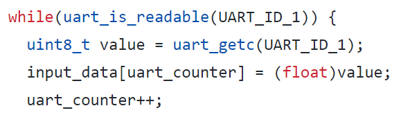
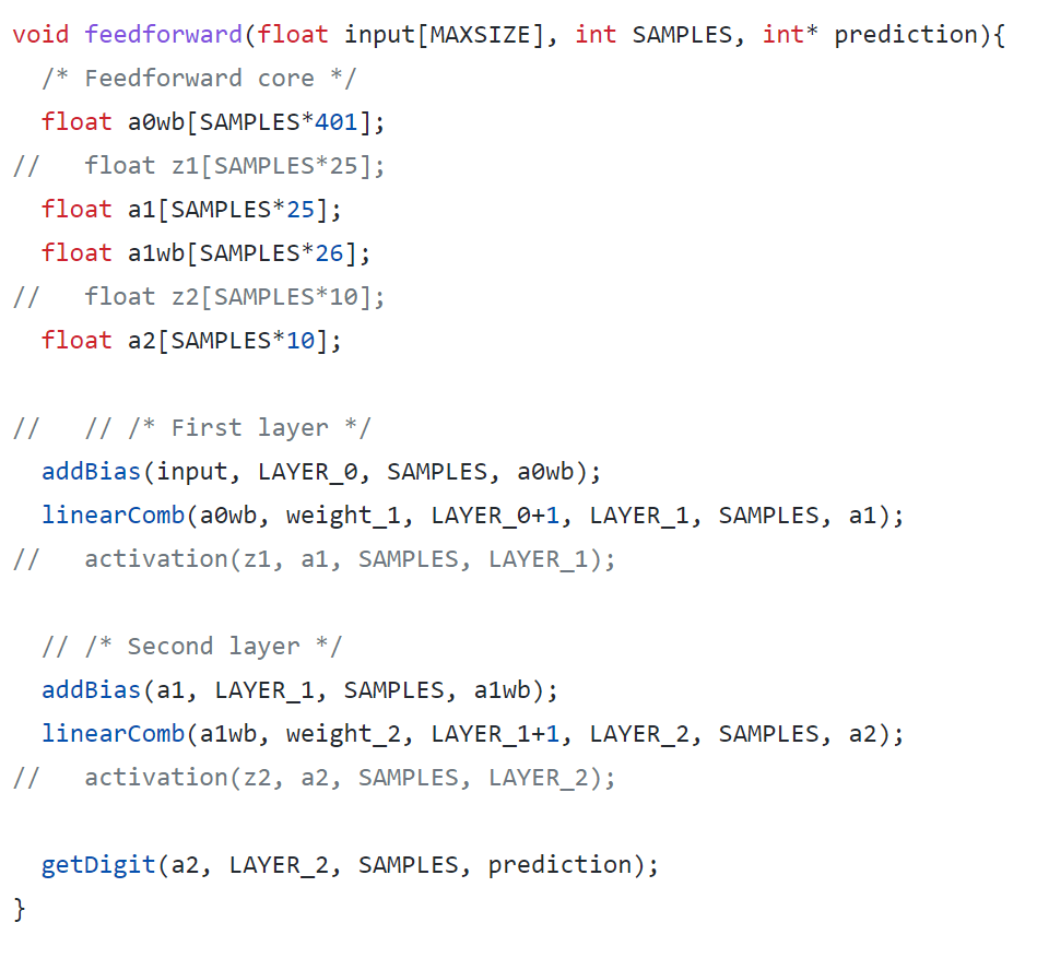
In the main loop of core 0 on the PICO, we set up a loop structure to listen for the signal sent from the laptop running the matlab script. The data is stored in an array and there is a counter used to keep track of the amount of data received. When all 400 bytes are received, we call the feedforward function, which implements the neural network to make the digit prediction. The feedforward function is composed of a series of function calls (as mentioned in the mathematical background section ) that takes the input data and makes the prediction. Each step of the network is modularized into a function and all the functions can take multiple input images so that the system can predict multiple digits at once (as much as the PICO stack allows). This is beneficial to our application because we are trying to predict a plate, which is composed of multiple digits.
Figure 17.
Plate Comparison
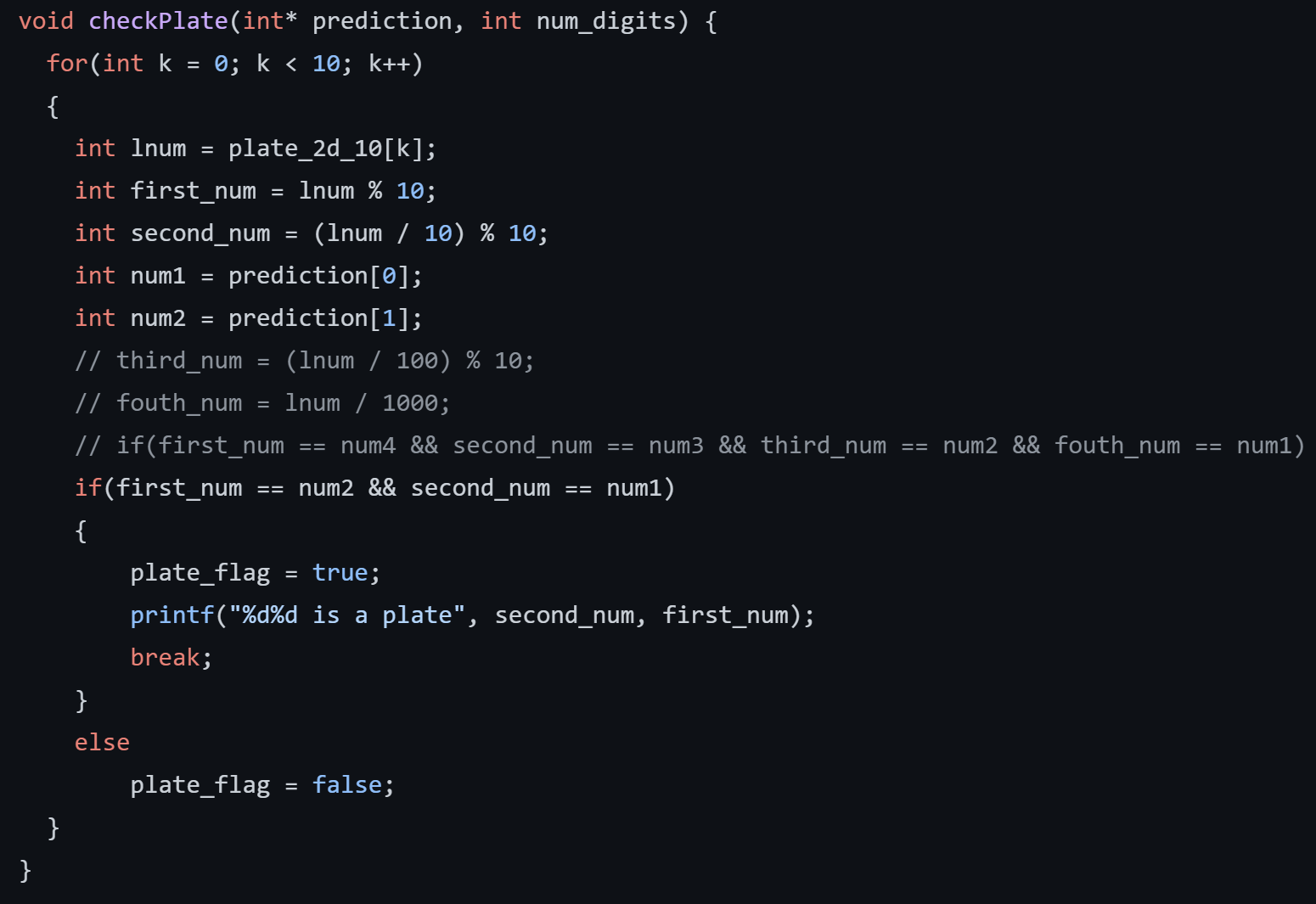
The plate_flag previously mentioned turns true when the recognized digits match a set within a given array. This is the portion of the project that acts like a ‘gate’ in a parking garage, checking to see if the plate matches that of a list that have already paid. The list is passed in as an array, and then compared to the predicted digits in a ‘checkPlate’ function figure 18.
Figure 18. checkPlate Function
The checkPlate function takes the two-digit number and then separates the first and the second digit through simple arithmetic operations. These are then compared to the predicted values, and if they are the same, the plate_flag turns true. An important part of this function is that after the plate_flag turns true, the function breaks from the for loop. One initial issue we ran into was that the plate_flag would turn true when the numbers matched, and then immediately turn false as the for loop compared the next number in the array. This happened so quickly that the LED did not appear to light up, and we believed that the issue was occurring elsewhere.
VGA
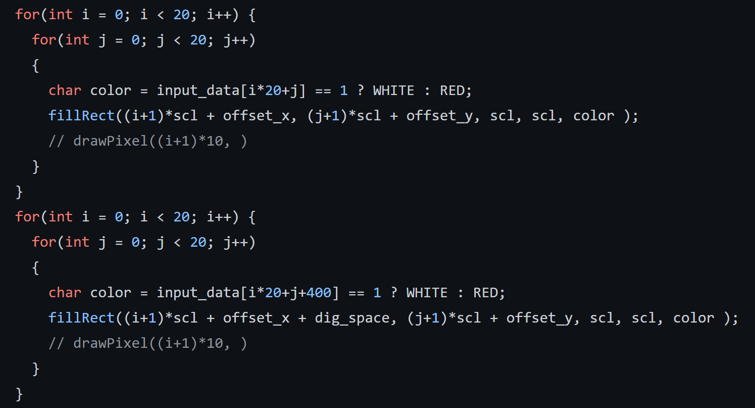
All VGA functionality takes place within a VGA protothread. Figure 19 shows a section of the protothread for displaying the drawn digits. For each digit, the code loops through a different section of the total bitmap array passed in, which is size of size (number of digits)*(400). The fillRect function is then used to create each section of the digits.
Figure 19. Section of VGA Thread for the Drawn Digits
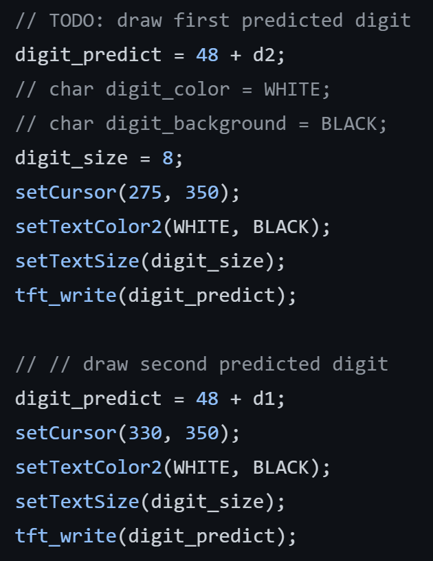
The next section of the protothread draws the predicted digits, as shown in figure 20. The ‘tft_write’ function uses ASCII to draw the desired digit on the VGA. So, the predicted numerical values of ‘d2’ and ‘d1’ first need to have 48 added to them to output the correct symbol.
Figure 20. Section of VGA Thread for the Predicted Digits
Iterative Threshold Selection Algorithm
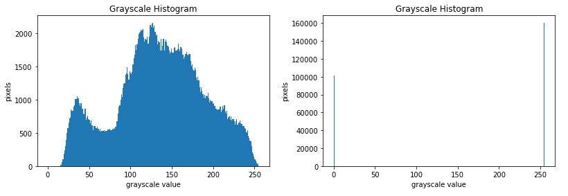
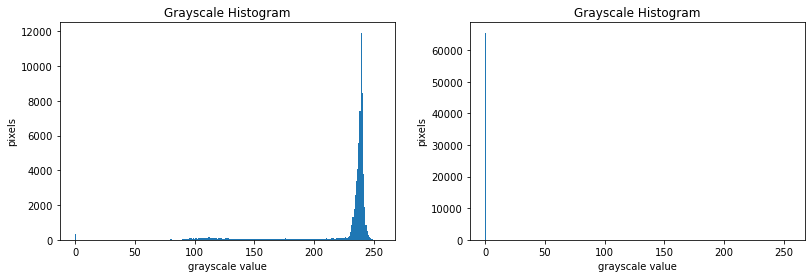
The camera output is in RGB format, and it is easier to convert it into grayscale image then binarize it into 0 and 255. But the processing power on the microcontroller is limited, so we want to binarize the grayscale image more efficiently to make the training and identification easier. Traditionally, there is a fixed threshold value, and the program processes the input image pixels one by one and separates them based on the fixed threshold value into either 0 or 255, as the first figure shows below. However, if the input image has tons of dark pixels or white pixels, this will not work, the fixed value threshold method will push all pixels to one side, causing the outcome to be a pure dark or pure white image, as the second figure shows below.
Figure 21. Even Distributed Image
Figure 22. Bias Pixel Distributed Image
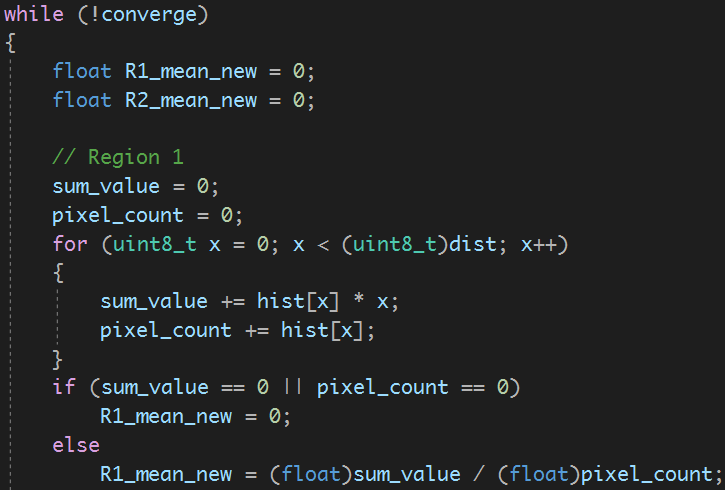
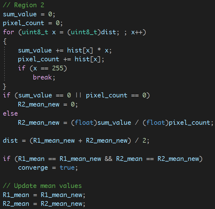
Therefore, to solve this issue, we use the iterative threshold selection algorithm. Following the steps below, instead of having a fixed threshold value, it calculates the threshold based on the histogram. The advantage of this is all image data considered in determining the threshold, is more robust.
Figure 23. Compute the mean of the two regions u1 and u2
Camera Registers
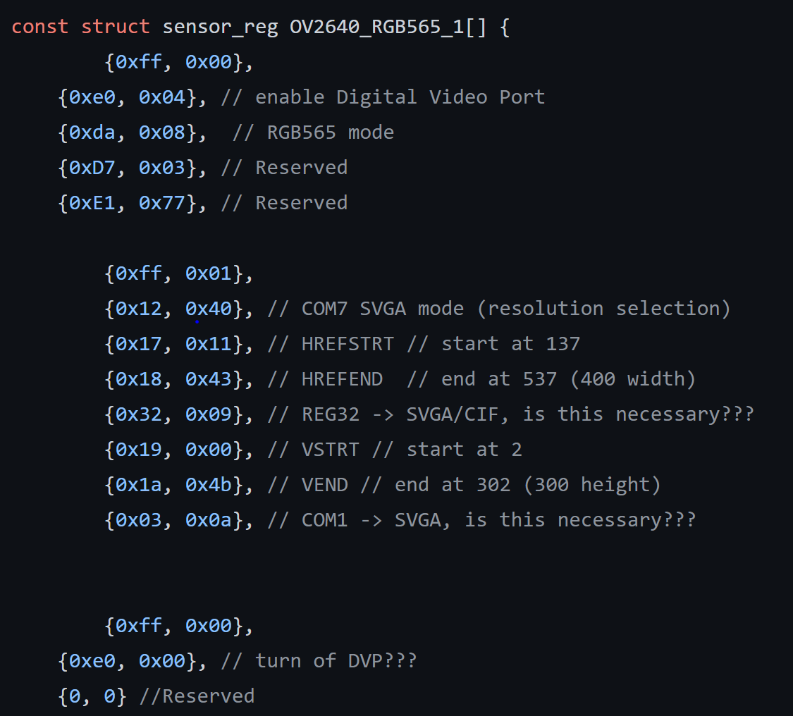
We were able to use demo code online with the camera to produce an image. We then ran into many difficulties in changing the camera settings so that its output would be an RGB565 array of consistent size. These settings relied on changing the camera’s registers, of which there is little documentation. Figure 24 shows an attempt at creating a header file to initialize the camera’s registers to the desired output.
Figure 24: Section of Arducam Header File for RGB65
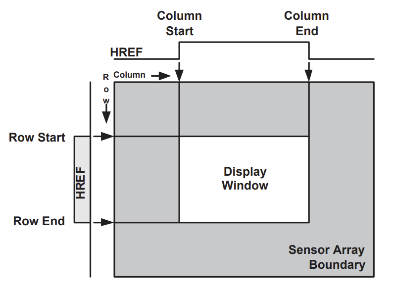
While we were able to initialize the output to be in RGB565, we ultimately could not control the size of the output array. Multiple attempts were made at understanding how the registers change the output array size, particularly with the ‘windowing’ functionality figure 25. According to documentation [9], the camera’s windowing is controlled by registers: HREFST, HREFEND, REG32, VSTRT, VEND, and COM1. Alterations to these registers did not produce the expected output, and altering other example code found online did not yield the expected results either.
Figure 25. Diagram of Windowing for OV2640 [9]
The final project successfully performed digit recognition from a digital drawing of two numbers and was able to use this recognition to complete an action, which in this case was turning on an LED. Although the system did not predict the digits with 100% accuracy, this was due to limitations in our training of the machine learning algorithm.
VGA Output
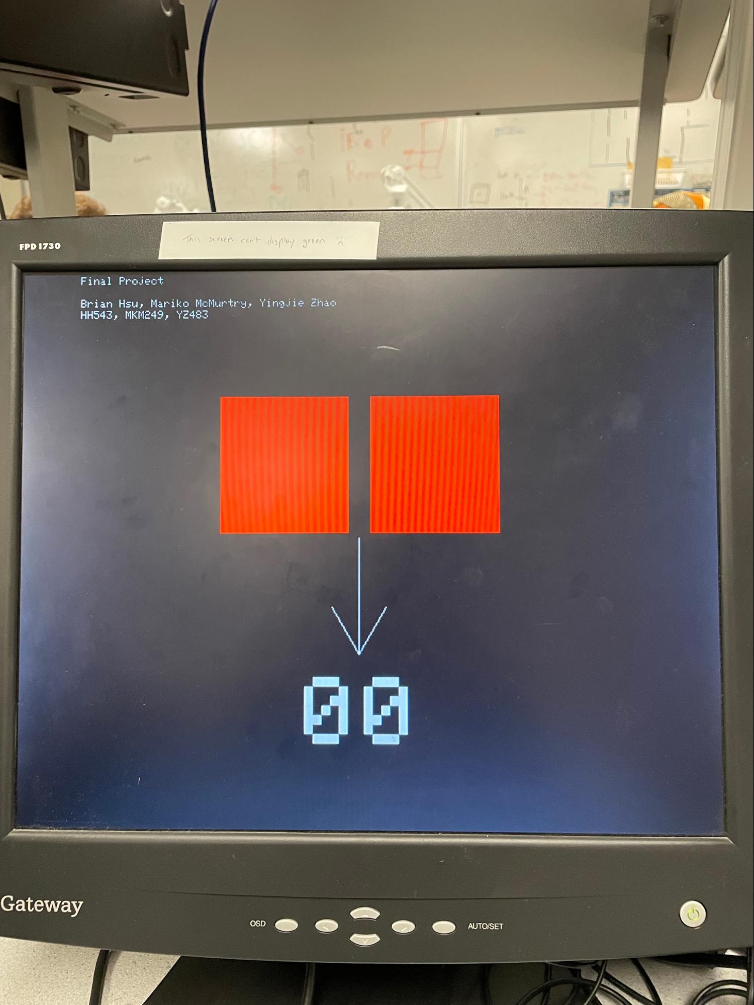
Before passing in any bitmaps, the VGA screen appears as figure 26. The two red rectangles are where the simplified bitmaps will be drawn , and the zeroes on the bottom will become the predicted digits.
Figure 26: Initial VGA Screen
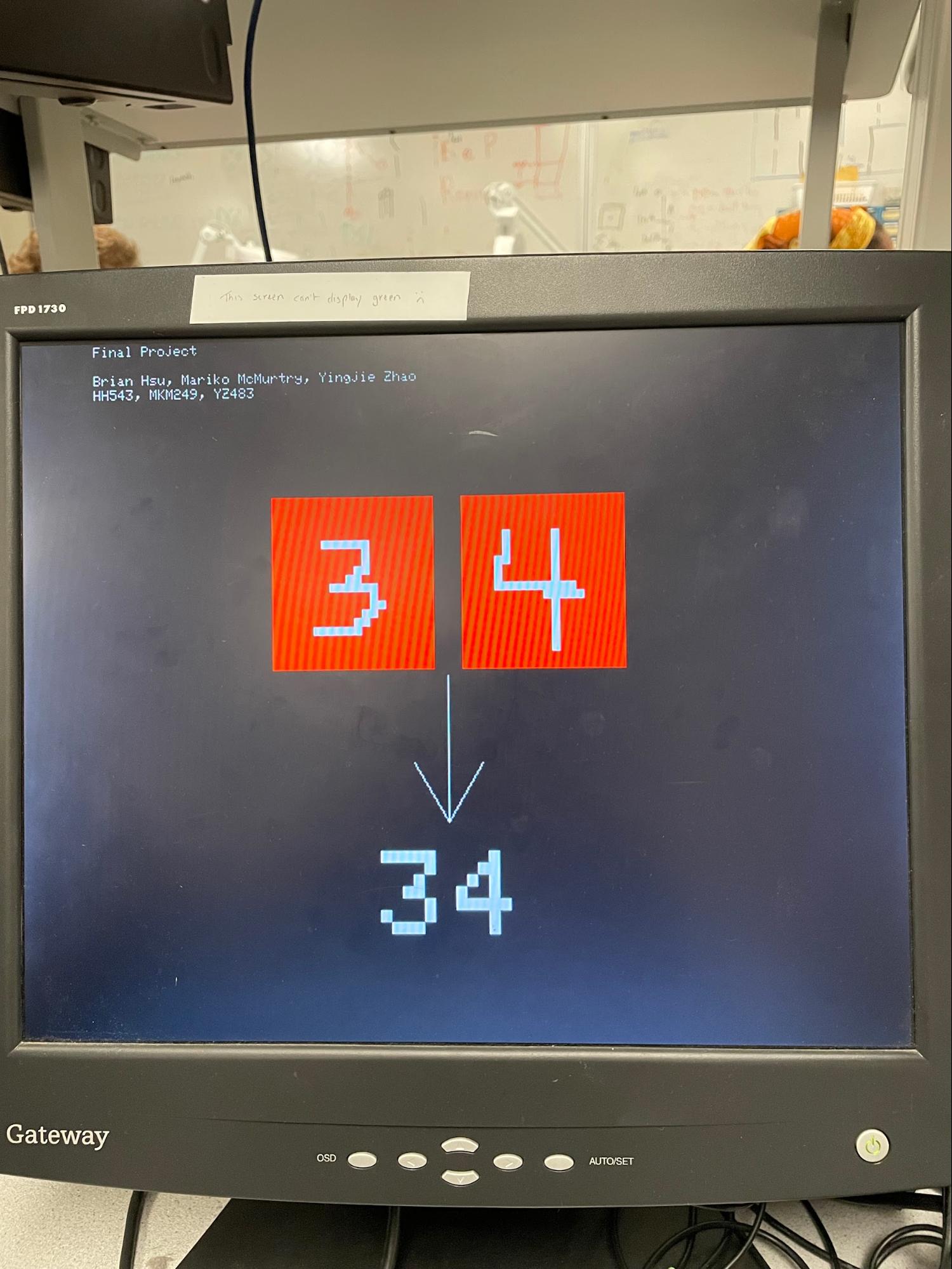
After passing through the bitmaps, the screen appears as in figure 27. The screen clearly shows that a “3” and “4” were drawn, and that algorithm could successfully predict these digits on the bottom. The total time for the digit recognition to take place and display on the VGA screen was a matter of seconds, but we did not actually time this.
Figure 27. VGA Screen After Digit Recognition
What Performed Poorly?
Currently, the system is limited to predicting two digits. It can be altered to predict only one, but three or more digits is not possible. With more than two digits, the system freezes and/or incorrectly predicts the digits. We believe this is due to the PICO running out of memory. Since we rely on a 20x20 bitmap array for each digit passed in to the PICO, another digit significantly increases the array size that the PICO has to handle. Further confirmation that it is a memory issue comes from one episode of debugging. We attempted to figure out why the system was freezing when implementing the digit recognition on the PICO, after it was working separately on a laptop. After simplifying the feedForward() function to get rid of a stack, thus decreasing the total necessary memory, the system began working as expected.
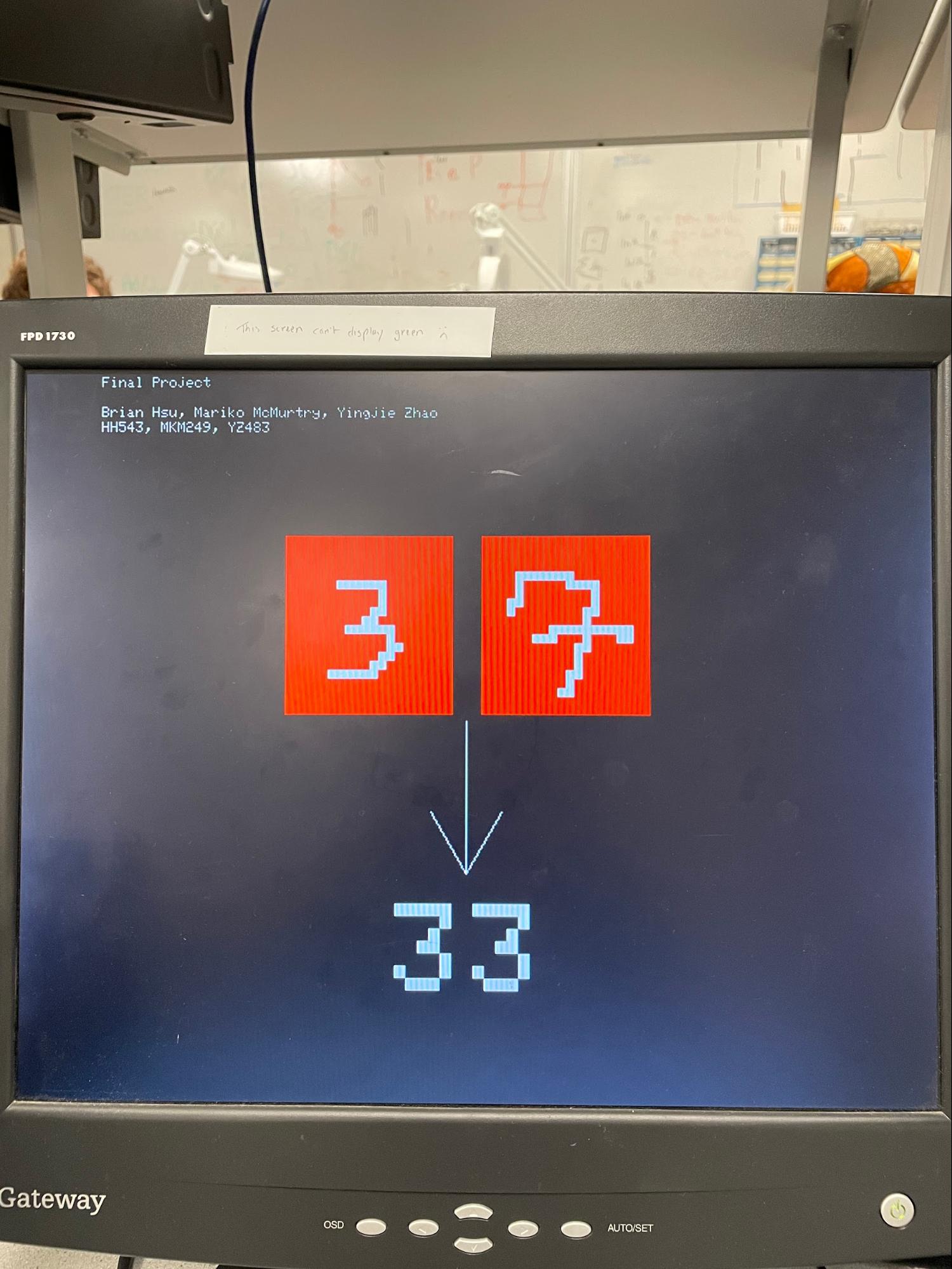
Additionally, while the system can accurately predict digits in many cases, it does not have 100% accuracy. Figure 28 shows one instance of this where “3” and “7” were drawn, but the system predicts “3” and “3”. Part of the reasoning for this is because the machine learning algorithm was initially made in MATLAB using type double. When transferred to the PICO, the algorithm had to be converted to floats. This difference of 8 bytes versus 4 bytes, decreased the accuracy of the algorithm. Also, training the algorithm with various hand-drawn digits might reduce some occasional error; however, that was out of the scope of this project.
Figure 28. VGA Screen After Digit Recognition
Design Safety and Usability
Overall, there is little to no concern for safety in the design. There is no physical movement in the system, no thermal aspect, or any part that could become harmful. This makes the system useable by nearly every person. Additionally, once the VGA is connected to the screen and the USB is plugged into the secondary laptop, the system runs with just two steps - simply drawing and saving the digital image in Paint, and then running the MATLAB script to downsize and pool the image. The PICO takes care of the rest. This makes it an easy to learn system that requires little instruction to start using. Ideally, in a real scenario where this is implemented in a parking lot, there would be no physical input from the user.
While the project did not fully meet our initial anticipation because the camera could not be implemented, the final system still works as a proof of concept for the license plate recognition. With more time to test out registers, the camera functionality could be implemented in the future to complete the system. Additionally, creating the algorithm with type floats in the future may improve accuracy. While being able to recognize more digits would be ideal, the limitations of the PICO memory seem to prohibit this at the moment.
The following are all taken from previous example code in the course and used in this project: vsync.pio, hsync.pio, vga_graphics.cpp, vga_graphics.h, rgb.pio, and pt_cornell_rp2040_v1.h. In addition to this code, we also utilized data from a machine learning course [10] to train our algorithm. Also, although we did not end up using the camera or its code, much of this code came from the demo code or other examples that are posted publicly online.
The group approves this report for inclusion on the course website.
The group approves the video for inclusion on the course youtube channel.
Code Reference: https://github.com/br1ansho3/pico_plate_recognition
[1] https://en.wikipedia.org/wiki/Multilayer_perceptron
[3] https://towardsdatascience.com/going-beyond-99-mnist-handwritten-digits-recognition-cfff96337392
[4] https://www.youtube.com/watch?v=aircAruvnKk&feature=youtu.be (3Blue1Brown Deep Learning)
[5] https://www.arducam.com/product/arducam-2mp-spi-camera-b0067-arduino/
[6] https://www.uctronics.com/download/Amazon/ArduCAM_Mini_2MP_Camera_Shield_DS.pdf
[7] https://www.uctronics.com/download/Amazon/B0067-B0068-Pico.pdf
[8] https://towardsdatascience.com/understanding-backpropagation-abcc509ca9d0
[9] https://www.uctronics.com/download/cam_module/OV2640DS.pdf
[10] https://www.coursera.org/learn/machine-learning-course/programming/AiHgN/neural-network-learning
[a]talk about the entire setup from matlab to camera to pico to vga..etc t
[b]on a highlevel, with diagrams probably