TETRIS
Christopher Chan (cc2698), Elizabeth Garner (emg229), James Pendergast (jcp327)
ECE 4760 Final Project
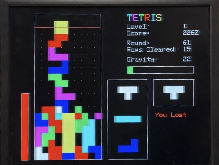
We recreated the classic game of Tetris in C on our RP 2040 Pico microcontroller to display the game on a VGA display and interface with buttons for user input.
For our final project, we wanted to select a video game that was widely popular and could be enjoyed by our peers at any skill level. As well, we saw this as a wonderful opportunity to work on a project involving heavy game logic. To create our version of Tetris, we created a state-machine with game logic, VGA animation, and button input in C. The state machine allowed us to maintain the state of the game, whether we were spawning a new piece, allowing the piece to fall, or losing the game. The VGA animation provided a clear gameplay interface and displayed stats like the game level, how fast pieces were moving, difficulty bar, and more. The button inputs allowed for an easily playable game with 5 different input options. Overall, we greatly enjoyed making a fun game that we could play and compete with friends on with an easy to use interface. We appreciated seeing friends discover the different features the game has that we had not previously paid much attention to playing online versions.
Our code revolved around a structure called tetris_game_t that would track all of the back-end information about the game as it was being played. This includes information like the state of the arena, the location of falling pieces, the speed at which pieces drop, and scoreboard information. Here is the code for that struct:
<script src="https://gist.github.com/cc2698/d84f25bcb82e5c39013271ebd0850a2d.js"></script>
Most of the functions in our code take a tetris_game_t as input. We create a volatile tetris_game_t at the top of our main file (tetris.c) which stores all of our game data.
Before discussing the details of how we implemented specific features in our game, we would first like to discuss elements of how our code was structured, and to outline some of the most important conventions we set for ourselves when developing this project.
We recognized that there were two main functionalities to our game, and primarily divided our code into two header files representing each of these functionalities.
The game_logic.h file contains all of the macros, enumerations, structs, and functions related to the back-end functionality of our game. Most of the manipulation of the values in our game are done by calling functions in this file.
The user_interface.h header file contains all of our functions that draw to the VGA screen. Functions in this file were responsible for handling all of the user interface elements of our game.
There was one core abstraction to respect when organizing code between these two files: functions in the game_logic.h file are not allowed to write to the VGA screen, and functions in the user_interface.h file may read, but not write, values to a tetris_game_t struct. Separating the code like this paved the way for a very intuitive structure to the code in our finite state machine. Every state of our machine respects the following code structure:
This was the most important coding convention that we established during the development of our project. All of our functionality is executed on a per-frame basis at a rate of 30 FPS (frames per second). Every frame, we check which state our FSM is in, and execute the functionality associated with that state. Organizing our code this way ensures that in each frame the game first recalculates its logic values, and then prints the result of those calculations to the VGA monitor.
Interleaving logical and visual operations left us prone to unpredictable visual artifacts resulting from having different UI elements refreshing with different data. This was the cause of a lot of visual bugs during our testing, including but not limited to pieces freezing, disappearing, or even leaving the arena entirely, as well as inconsistencies between the gameplay and the scoreboard. Ensuring that data stays constant during each visual refresh guarantees that every element of the UI updates with the same data. Not only did this make the game more robust, but it also significantly improved the debugging process.
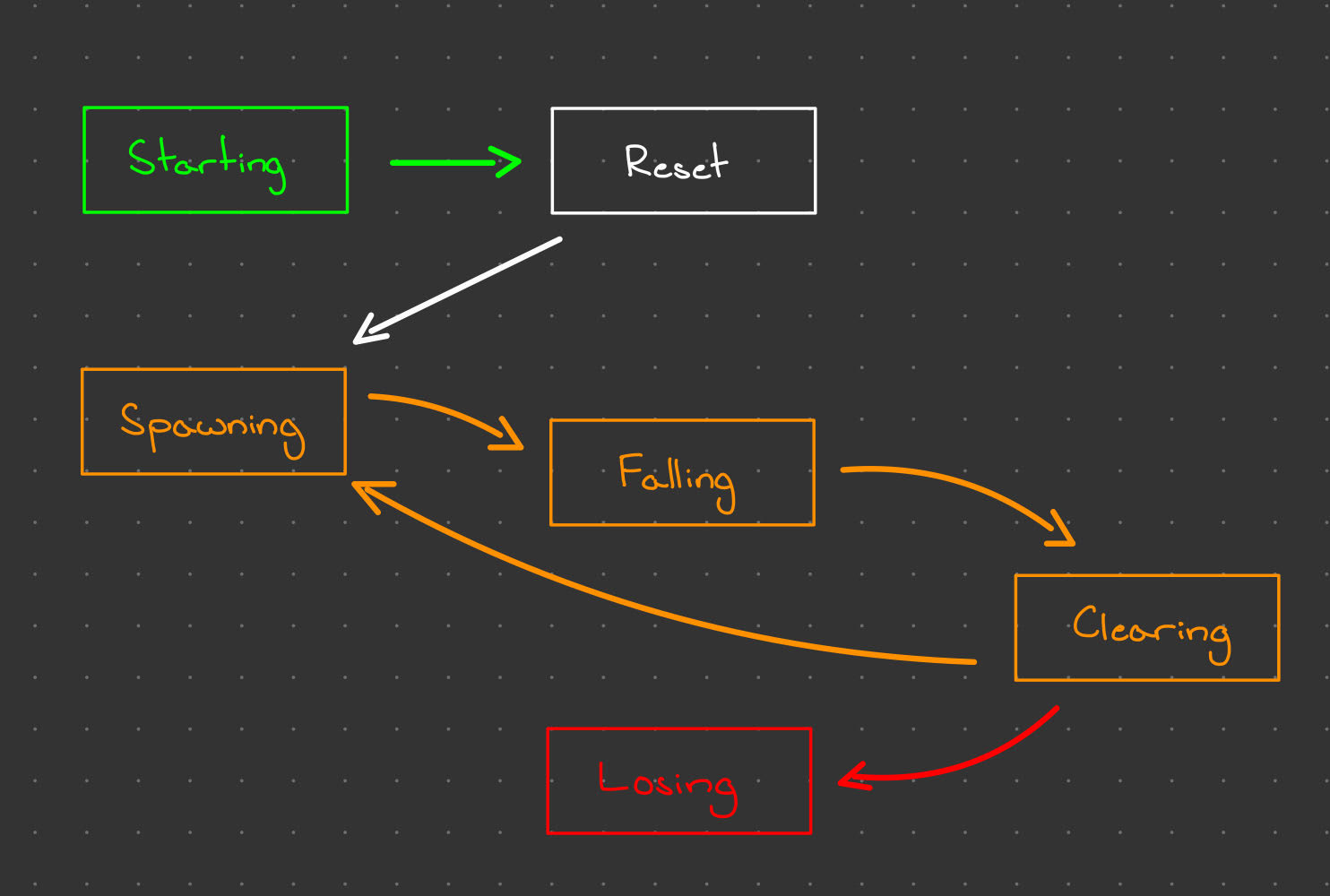
Our finite state machine has 6 states:
Here is a brief overview of what each state does:
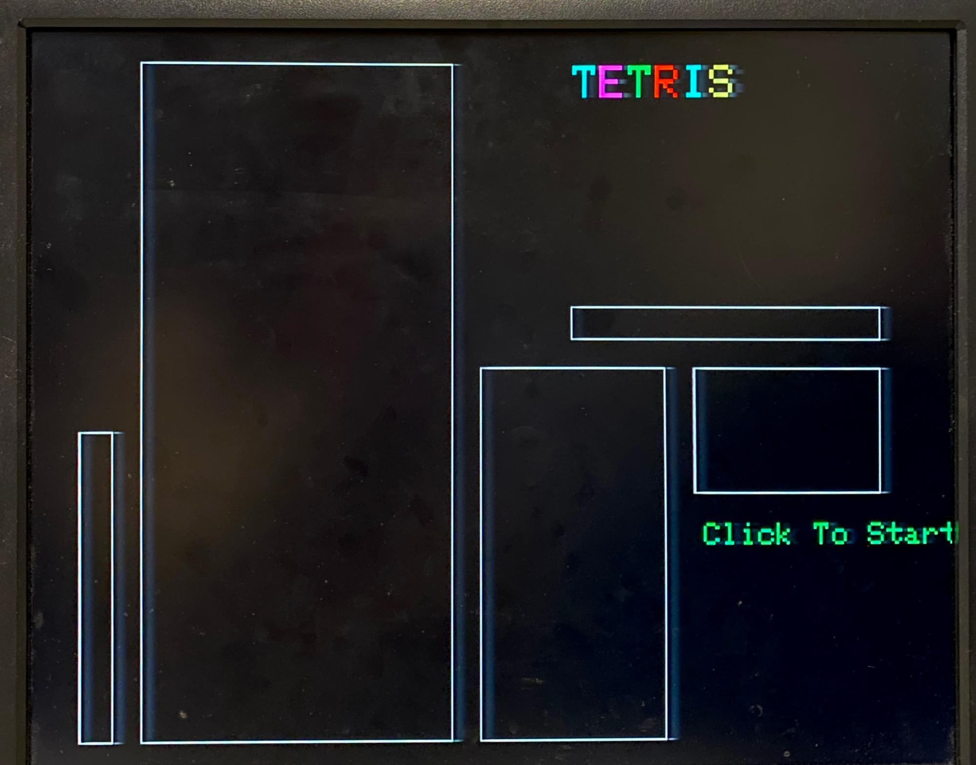
The FSM starts in the START state, which waits for user input before proceeding to the RESET state. In the RESET state, the game is initialized with default values and the scoreboard is reset. Gameplay begins once the FSM transitions from the RESET state to the SPAWNING state.
During gameplay, the FSM loops through the SPAWNING, FALLING, and CLEARING states, repeating the falling state until the piece hits the ground. One iteration through this set of states replicates one round of tetris: the game spawns a piece, drops that piece to the ground, and checks if any rows need to be cleared.
If during the CLEARING state, it is discovered that the player has lost the game, the FSM advances to the LOSING state. If the player chooses to restart the game, the FSM transitions back to the reset state
We have two threads in our project, protothread_anim and protothread_keypad, both scheduled to execute at regular intervals. The animation thread schedules at 30Hz, and runs the state machine described above. All of our game logic and VGA drawing takes place in the animation thread. The keypad thread schedules at a much faster (probably unnecessarily fast) 10KHz, and polls the GPIO pins to determine if they are pressed. A set of flags indicating if the GPIO pins are pressed or held are modified accordingly. The only exception to the above division of functionality is that if the soft-drop button is pressed, the keypad thread modifies the game’s gravity directly. These two threads are always active.
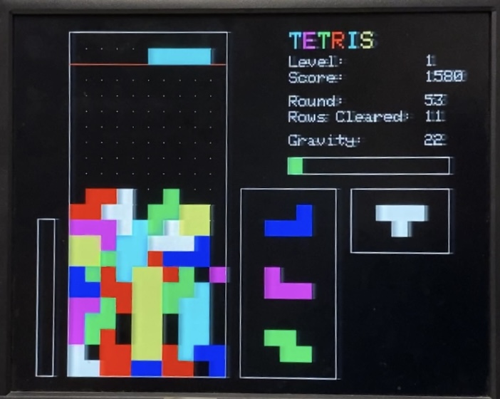
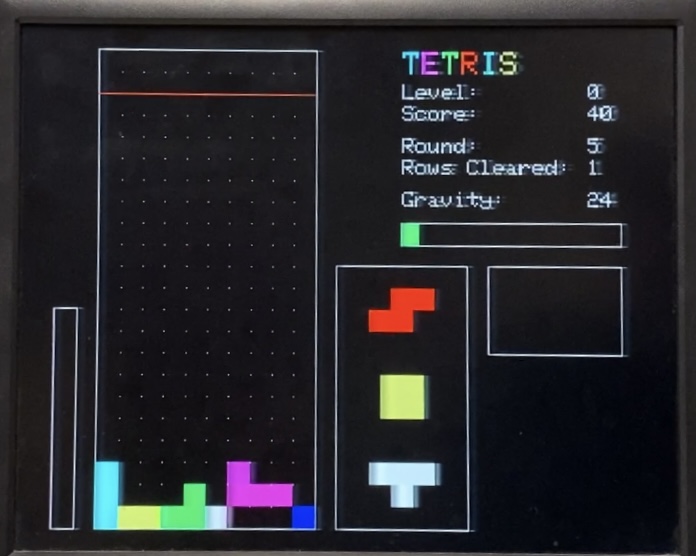
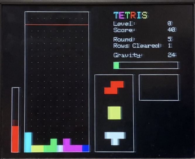
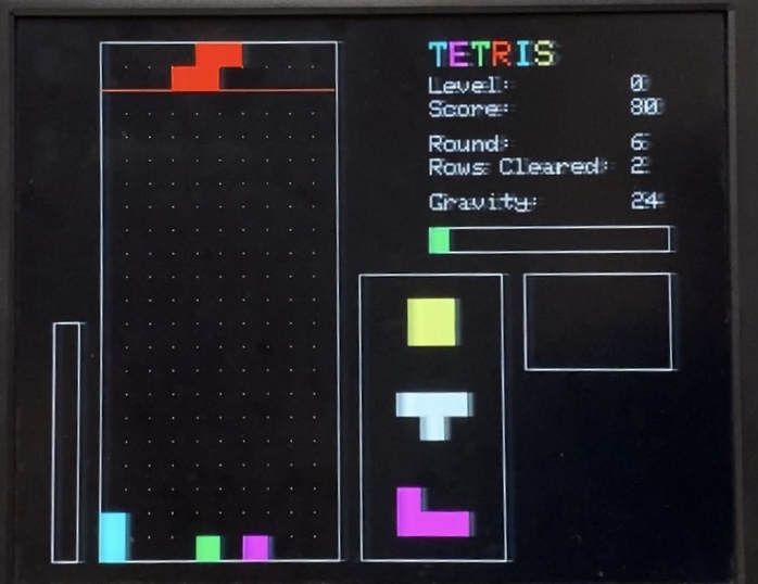
The arena for the game is a grid of 22 by 10 units that saves the piece number, color, and type. Since there are eight colors available on the VGA in our current setup, this worked out wonderfully as there is a color for each of the seven tetris pieces and black for an empty square. The status of each unit of the grid is maintained in a two-dimensional arena. Every unit is 20 pixels by 20 pixels as this was visually nice without taking up too much space on the VGA display. As well, the arena and grid are created relative to each other. It can be expanded, shrunk, or moved in any direction with changes to the variables for the number of pixels associated with each unit or the (x, y) coordinate for the top left corner of the arena, respectively.
Tetris is already in existence with the associated name, colors, shapes, and game logic. There are many fan recreations of Tetris online and available to play.
As outlined above, we defined conventions for how we were going to organize our code to prevent bugs. At the highest level of abstraction, our code executes the finite state machine implemented in the animation thread. As discussed above, each state abides by the following structure:
Here is an example of how the CLEARING state of our FSM was designed:
<script src="https://gist.github.com/cc2698/dfd7b19b84caba1c383c39c789fa5b69.js"></script>
Abstracting most of the functionality into logic and UI helper functions streamlined our implementation tremendously. It allowed us to keep the code in our FSM thread focused on the higher level organization of the features in tetris, leaving the actual implementation of each function hidden.
There were some initial complications that we faced when designing our input processing. Most predominantly, because inputs were handled every frame, we needed a method of tracking whether a button press was valid. Without a clever implementation, it was impossible to control how much the pieces were moving side-to-side and rotating.
The implementation that we came up with was to have a pair of flags for each input, tracking whether a button had been pressed and whether an existing button press was valid. The state of the flags was updated as follows. For any given button:
The idea behind this implementation was to track whether a button press had been handled, and invalidate that action until the associated button had been released. The button_valid flag is set false when the action is performed, and only becomes true again once the button is released.
Rotations were perhaps the trickiest part of the project to implement. As discussed below, the rotation system for tetris is complicated. Not every piece has a grid-aligned center of rotation. Furthermore, if the player rotates a piece such that parts of the piece are out-of-bounds, or intersect with other pieces, the game tries to bump the piece away from the wall (within reason) to avoid collisions. With all of that in mind, we tried to take a very formulaic approach to rotation.
The core idea behind our rotation system is that the post-rotation coordinates of each cell can be calculated as a rotation around the center of rotation using the same formulas that apply to points in a cartesian xy-plane. This allowed us to apply the same rotation code to all of the pieces so long as we kept track of the x and y coordinates of the rotational center. We use the center_x and center_y fields of the tetris_game struct to do this. Here is the code that we used for these rotations:
<script src="https://gist.github.com/cc2698/81ea27315365afcbe1a3adc9d5c1e2ff.js"></script>
Note that piece_is_valid() is another function in our game_logic.h file. Here was the specification for that function:
<script src="https://gist.github.com/cc2698/e018760e359bfbcaefe8c209ce1f541a.js"></script>
If the normal unadjusted rotation is invalid, we proceed to check a few configurations that check if adjusting the post-rotation coordinates by one cell (or up to two cells for a 1-by-4 “I Piece”) either left, right, or up, would make a valid configuration. We do this by creating potential locations for the adjusted location, and choosing one that is valid. The full code for this is too long to include in a snippet, but can be found in the rotate_CCW() function in game_logic.c. Here is a snippet modeling how we would achieve this sort of behavior for just one of the three directions:
<script src="https://gist.github.com/cc2698/601988b1d673308e3d6ad2388eeae7b1.js"></script>
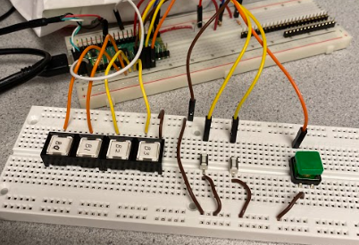
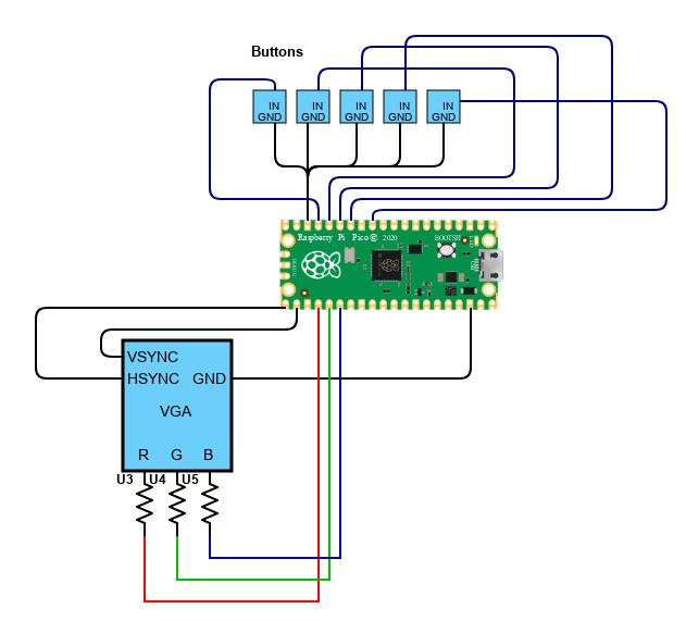
For the hardware aspect of this project, we used a set of five buttons for each of the associated user inputs. The button inputs are Move Left, Move Right, Rotate Clockwise, Move Down Quickly, Hold Piece, and Start Game. Each button is wired between ground and an associated GPIO pin on the RP 2040 Pico. We also had to establish the VGA interface to display our tetris game.
To establish connections between buttons and our microcontroller, we utilized the RP2040 Pico’s GPIO functionality. GPIO pins are able to read and set the values of digital inputs and outputs, allowing us to perform certain actions when those values are found. The Pico datasheet states that there are 36 available GPIO pins, so we had more than enough to satisfy our needs for tetris. Here is a picture of our button circuit. We ended up reducing the button amount to 5 after realizing some were unneeded.
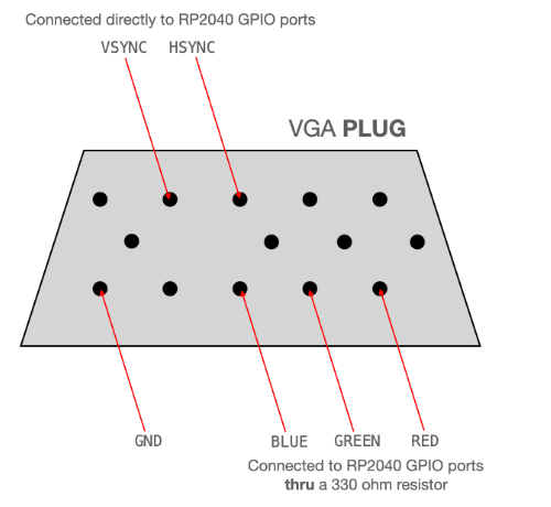
Regarding the VGA protocol, driving the screen requires two digital synchronization pins and three analog color pins for red, green, and blue.One of the sync pins is HSYNC, which communicates when to move to a new row of pixels. The other sync pin is VSYNC which is responsible for starting new frames. At a lower level the protocol is even more involved, as each of the sync pins as well as the RGB pins are driven with PIO state machines through a DMA channel. The image below displays the pins that were used on the VGA adapter.
After combining the GPIO connections for user input, as well as the VGA protocol for display, we had enough hardware to complement the extensive software for our tetris game. Displayed below is the complete hardware schematic for the circuit.
The trickiest parts were committing to a general structure for how to represent our pieces and rotations. We were very careful in the beginning of the programming process to properly discuss and plan how we were going to represent features in code down the line. We outlined the features we were looking to include in our project to come up with the cleanest way to encode them. As described above, rotation was difficult. There was much discussion on doing the math for each rotation within the program or to hardcode all 28 possible positions across the seven pieces and then calling upon each of them. We ended up going with the math approach because it allowed for more flexibility and less code redundancy. The main issue with hardcoding was rotating next to other pieces and making sure that each square in the arena was not lost or overwritten.
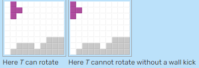
As well, wall kicks needed to be added for complete accuracy. These were introduced to the game in 2001. Wall kicks come into play when a piece is progressing down the arena alongside the wall and the user is trying to rotate it. Prior to wall kicks, the piece could not be rotated as it does not have enough space to move anywhere. After the introduction of wall kicks, the piece can be rotated and will push itself towards the middle of the arena to give just enough space to full turn. This allows for more enjoyable gameplay as the user has more flexibility when it comes to rotation. Wall kicks added to our needed math for rotation, making our math-oriented solution easier relative to our main alternative.
We did not use a scope or waveforms for our debugging. The VGA and buttons were the only hardware associated with the RP 2040 in our project. Since each member of the team had experience with both part types and the pieces were simple, we did not run into hardware issues that required debugging.
For software debugging, we played a lot of Tetris. Like a LOT of Tetris. At the beginning of our project, we each needed to become more familiar with actual Tetris and its rules. We read online rules, the reddit page r/tetris, the fandom wiki, and played the available versions on different websites for hours. If we had any misconceptions about how Tetris should work, these would come up in our final project. Therefore, it was very important for us to allot time to researching the game and its background.
Once we started testing our actual game, we played it again and again. We had to ensure that each feature worked in a variety of situations like clearing multiple rows, clearing non-neighboring rows, rotating against different types of pieces and the boundaries, losing with different configurations, and so on. Every time we added a feature, we had to make sure that each of the previous features still worked.
All around, the game is very responsive to user input. There is no visible delay between a button press and the related change on the VGA display. Especially since we overclocked our Pico, we are reading in button data and drawing to the VGA display very quickly.
Overall, we were conservative with rewriting the VGA screen. When a piece is moving down the arena, only that piece gets redrawn at the associated frame rate at that time. As a result, the piece moving down the arena occasionally flickers. This could be stopped if the redraw rate did not overlap with the VGA refresh rate. However, the frames per update is changing throughout the game as the player moves up the levels. Therefore, we decided that the user experience was more important than preventing an occasional flicker of the one piece moving down the screen. The pieces that have accumulated at the bottom and are set in place only get redrawn when a row is cleared. These pieces do not experience a flicker, unless the row clearing happened to align with the VGA refresh. This is difficult to control as row clearing can happen at any time and needs to be done immediately for proper game play experience for the user.
During our project, safety was not a major risk. Since these specific buttons have been used previously in other projects, we could be comfortable that they did not pose a risk for others to use. As well, we spread our wiring across two boards so that it was clear where the user input was and to keep players from touching any circuitry besides their buttons.
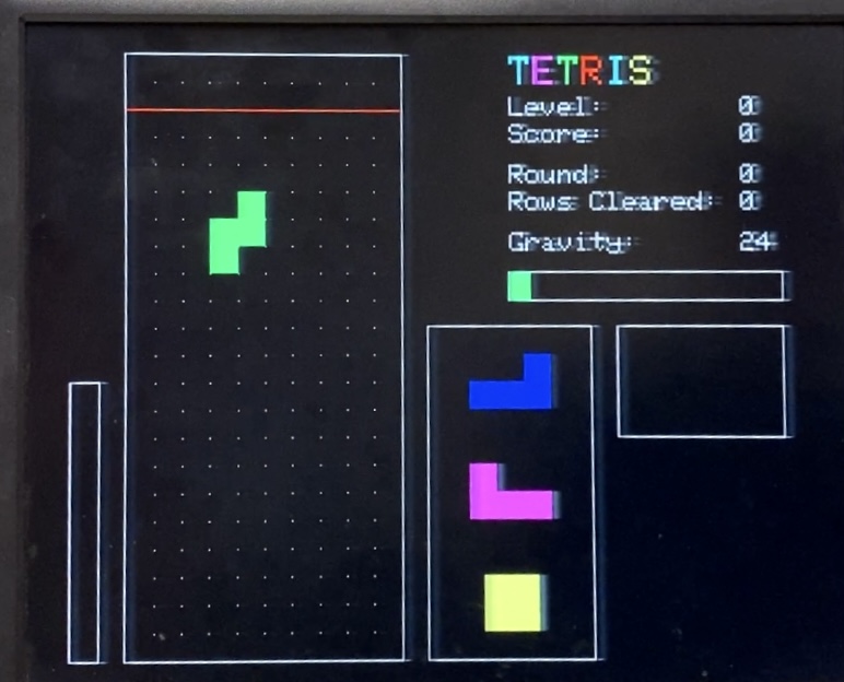
Usability was an important part of our project as our goal was to recreate an enjoyable experience for all. We had many people play (I mean test) our game, including Bruce Land!!! We made sure that our user interface was drawn with easy to read colors and that the grid was very clear to the player. As well, we tried to include many pieces of information for the player to look at if they wanted to (level, score, round, frames per drop, time left before a piece set, difficulty bar, three upcoming pieces in order, and piece being held).
Our final product closely matched the design we had set out to create. The responsiveness to user input was very important to the success of our project, in our eyes. Towards the beginning of the project, we created a long list of features broken down into Phase 1 and Phase 2. The first phase was comprised of the features that we deemed necessary in order for the game to resemble basic Tetris. Phase 2 included features that we would be happy to include, given that there was time. With this system, we were able to break down our project into smaller goals and make our large, detailed project more achievable to us. We could better prioritize features based on their importance to creating a playable Tetris game. As well, we could keep our focus for the additional features we were excited to include.
Next time, it would be cool to include two-player. While writing our initial Phase 1 and Phase 2 plans, one of our main Phase 2 goals was to make it multiplayer. As the project progressed, we had to decide between prioritizing classic Tetris features and two-player. We chose to prioritize other features as there are so many possibilities to add with the many years that Tetris has existed. As well, being thorough in our testing is time consuming, but is ultimately more important to our original vision than two-player.
We did not use any code external to what is included in the course. In our program, we utilize the libraries used during the semester in our prior labs. As well, we used snippets of code from our previous labs in this course, such as the Boids lab, as a starting point for our design.
Since our project was to recreate an already existing game, we did need to reverse-engineer our design. This meant that we played the game many times and thought critically about how the pieces could be manipulated, how the arena could be represented, and which features we wanted to prioritize. We did not read other people’s source code to design our project, although there is some probably available online.
We did not sign a non-disclosure agreement as part of our project. Since the game exists already, there are no patent opportunities for our project.
The above images include the following in order:
The group approves this report for inclusion on the course website.
The group approves the video for inclusion on the course youtube channel.
Hardware design to interface buttons and VGA display with RP 2040 Pico.
Part Name | Cost in Dollars |
RP 2040 Pico | 4 |
Assorted Buttons (found around the lab) | ~0.20 each, 1.20 total |
Total Cost | 5.20 |
Chris: Determined rotation scheme for pieces, established arena grid, ensured “random bag” spawning, organized code behind the state machine.
James: Researched and worked on Scoring system, established the losing state, maintained GPIO hardware and VGA connection, designed some of the VGA interface details.
Elizabeth: Programmed ability for all 8 pieces to correctly spawn, established connections between buttons and software for moving pieces, added wall kicks to SRS scheme.
Data Sheets
Vendor and Background Sites
Webpage Link: https://pages.github.coecis.cornell.edu/emg229/ECE4760_Final/